- 您現(xiàn)在的位置:買賣IC網(wǎng) > PDF目錄45002 > LW016BK1 (LINEAGE POWER LLC) 2-OUTPUT 16 W DC-DC REG PWR SUPPLY MODULE PDF資料下載
參數(shù)資料
| 型號: | LW016BK1 |
| 廠商: | LINEAGE POWER LLC |
| 元件分類: | 電源模塊 |
| 英文描述: | 2-OUTPUT 16 W DC-DC REG PWR SUPPLY MODULE |
| 封裝: | MODULE-9 |
| 文件頁數(shù): | 15/16頁 |
| 文件大小: | 486K |
| 代理商: | LW016BK1 |
88
Lineage Power
Advance Data Sheet
April 2008
36 Vdc to 75 Vdc Inputs; 16 W
LW016 Dual-Output-Series Power Modules:
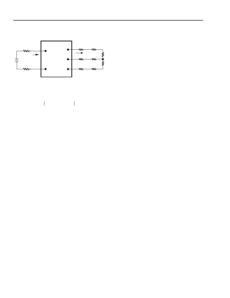
Test Configurations (continued)
8-863(C).a
Note: All measurements are taken at the module terminals. When
socketing, place Kelvin connections at module terminals to
avoid measurement errors due to socket contact resistance.
Figure 9. Output Voltage and Efficiency
Measurement Test Setup
Design Considerations
Grounding Considerations
For modules without the case ground pin option, the
case is connected internally to the VI(+) pin. For mod-
ules with the case ground pin option, device code
suffix “7,” the case is not connected internally allowing
the user flexibility in grounding.
Input Source Impedance
The power modules should be connected to low ac-
impedance input sources. Highly inductive source
impedances can affect the stability of the power mod-
ules. For the test configuration in Figure 7, a 33 F
electrolytic capacitor (ESR < 0.7 at 100 kHz)
mounted close to the power module helps ensure sta-
bility of the unit. For other highly inductive source
impedances, consult the factory for further application
guidelines.
Safety Considerations
For safety-agency approval of the system in which the
power module is used, the power module must be
installed in compliance with the spacing and separation
requirements of the end-use safety agency standard,
i.e., UL 1950, CSA C22.2 No. 950-95, and VDE 0805
(EN60950, IEC950).
If the input source is non-SELV (ELV or a hazardous
voltage greater than 60 Vdc and less than or equal to
75 Vdc), for the module's output to be considered
meeting the requirements of safety extra-low voltage
(SELV), all of the following must be true:
n
The input source is to be provided with reinforced
insulation from any other hazardous voltages, includ-
ing the ac mains; and
n
One VI pin and one VO pin are to be grounded or
both the input and output pins are to be kept floating;
and
n
The input pins of the module are not operator acces-
sible; and
n
Another SELV reliability test is conducted on the
whole system, as required by the safety agencies, on
the combination of supply source and the subject
module to verify that under a single fault, hazardous
voltages do not appear at the module's output.
Note: Do not ground either of the input pins of the
module without grounding one of the output
pins. This may allow a non-SELV voltage to
appear between the output pins and ground.
The power module has extra-low voltage (ELV) outputs
when all inputs are ELV.
The input to these units is to be provided with a maxi-
mum 5 A normal-blow fuse in the ungrounded lead.
Feature Descriptions
Overcurrent Protection
To provide protection in a fault (output overload) condi-
tion, the units are equipped with internal current-limiting
circuitry and can endure current limiting for an unlim-
ited duration. At the point of current-limit inception, the
units shift from voltage control to current control. If the
output voltage is pulled very low during a
severe fault, the current-limit circuit can exhibit either
foldback or tailout characteristics (output-current
decrease or increase). The units operate normally once
the output current is brought back into its specified
range.
VI(+)
II
IO
SUPPLY
CONTACT
RESISTANCE
CONTACT AND
DISTRIBUTION LOSSES
LOAD
VI(-)
VO1
VO2
COM
LOAD
η
VOJ
COM
–
[]IOJ
J1
=
2
∑
VI +
() VI –
()
–
[]II
-----------------------------------------------------x 100
%
=
相關(guān)PDF資料 |
PDF描述 |
|---|---|
| LW016AJ7 | 2-OUTPUT 16 W DC-DC REG PWR SUPPLY MODULE |
| LW016AJ1 | 2-OUTPUT 16 W DC-DC REG PWR SUPPLY MODULE |
| LW016BK8 | 2-OUTPUT 16 W DC-DC REG PWR SUPPLY MODULE |
| LW016AJ3 | 2-OUTPUT 16 W DC-DC REG PWR SUPPLY MODULE |
| LW016BK3 | 2-OUTPUT 16 W DC-DC REG PWR SUPPLY MODULE |
相關(guān)代理商/技術(shù)參數(shù) |
參數(shù)描述 |
|---|---|
| LW016BK3 | 制造商:未知廠家 制造商全稱:未知廠家 功能描述:Analog IC |
| LW016BK7 | 制造商:未知廠家 制造商全稱:未知廠家 功能描述:Analog IC |
| LW016BK8 | 制造商:未知廠家 制造商全稱:未知廠家 功能描述:Analog IC |
| LW016CL | 制造商:未知廠家 制造商全稱:未知廠家 功能描述:DC-to-DC Voltage Converter |
| LW016CL1 | 制造商:未知廠家 制造商全稱:未知廠家 功能描述:Analog IC |
發(fā)布緊急采購,3分鐘左右您將得到回復(fù)。