- 您現(xiàn)在的位置:買賣IC網(wǎng) > PDF目錄358961 > LV2205 (ON SEMICONDUCTOR) Silicon Tuning Diodes PDF資料下載
參數(shù)資料
| 型號: | LV2205 |
| 廠商: | ON SEMICONDUCTOR |
| 元件分類: | 參考電壓二極管 |
| 英文描述: | Silicon Tuning Diodes |
| 中文描述: | 15 pF, 25 V, SILICON, VARIABLE CAPACITANCE DIODE, TO-92 |
| 封裝: | PLASTIC, CASE 182-06, TO-226AC, 2 PIN |
| 文件頁數(shù): | 1/8頁 |
| 文件大?。?/td> | 70K |
| 代理商: | LV2205 |
Semiconductor Components Industries, LLC, 2001
October, 2001 – Rev. 3
1
Publication Order Number:
MMBV2101LT1/D
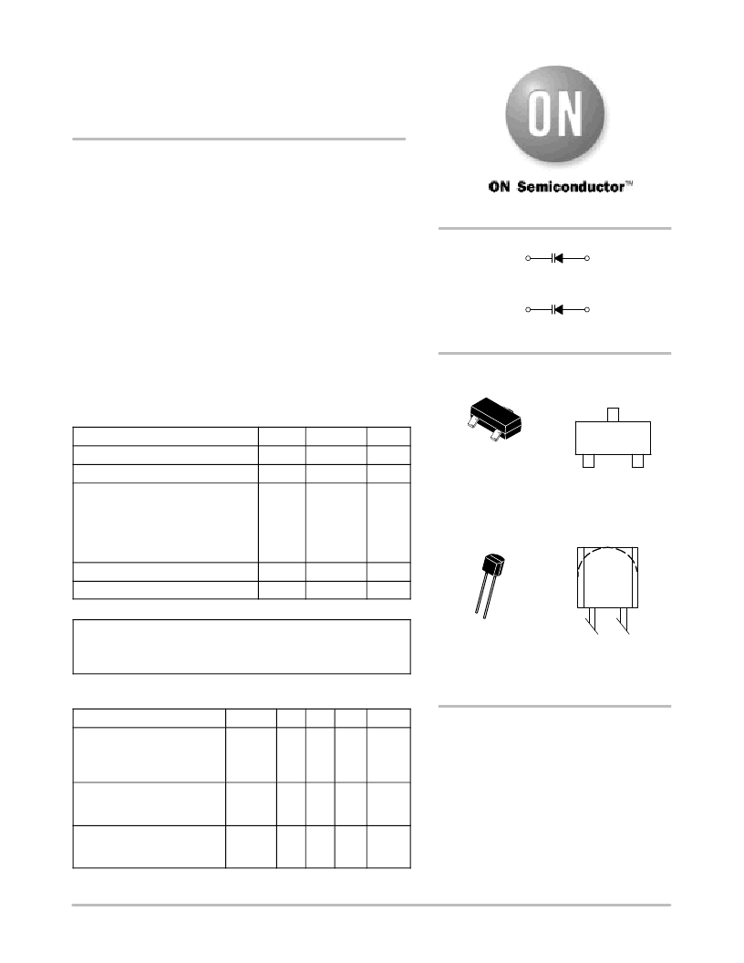
MMBV2101LT1 Series,
MV2105, MV2101, MV2109,
LV2205, LV2209
Silicon Tuning Diodes
6.8–100 pF, 30 Volts
Voltage Variable Capacitance Diodes
These devices are designed in popular plastic packages for the high
volume requirements of FM Radio and TV tuning and AFC, general
frequency control and tuning applications. They provide solid–state
reliability in replacement of mechanical tuning methods. Also
available in a Surface Mount Package up to 33 pF.
High Q
Controlled and Uniform Tuning Ratio
Standard Capacitance Tolerance – 10%
Complete Typical Design Curves
MAXIMUM RATINGS
Rating
Symbol
Value
Unit
Reverse Voltage
VR
IF
PD
30
Vdc
Forward Current
200
mAdc
Forward Power Dissipation
@ TA = 25
°
C
Derate above 25
°
C
MMBV21xx
@ TA = 25
°
C
Derate above 25
°
C
MV21xx
LV22xx
225
1.8
280
2.8
mW
mW/
°
C
Junction Temperature
TJ
Tstg
+150
°
C
Storage Temperature Range
–55 to +150
°
C
DEVICE MARKING
MMBV2101LT1 = M4G
MMBV2103LT1 = 4H
MMBV2105LT1 = 4U
MMBV2107LT1 = 4W
MMBV2108LT1 = 4X
MMBV2109LT1 = 4J
MV2101 = MV2101
MV2105 = MV2105
MV2109 = MV2109
LV2205 = LV2205
LV2209 = LV2209
ELECTRICAL CHARACTERISTICS
(TA = 25
°
C unless otherwise noted)
Characteristic
Symbol
Min
Typ
Max
Unit
Reverse Breakdown Voltage
(IR = 10
μ
Adc)
MMBV21xx, MV21xx
LV22xx
V(BR)R
30
25
–
–
–
–
Vdc
Reverse Voltage Leakage
Current
(VR = 25 Vdc, TA = 25
°
C)
IR
–
–
0.1
μ
Adc
Diode Capacitance
Temperature Coefficient
(VR = 4.0 Vdc, f = 1.0 MHz)
TCC
–
280
–
ppm/
°
C
http://onsemi.com
Preferred
devices are recommended choices for future use
and best overall value.
MARKING
DIAGRAM
3
Cathode
1
Anode
2
Cathode
1
Anode
SOT–23
TO–92
1
2
3
1
2
XX
XXXX
YWW
TO–226AC, TO–92
CASE 182
STYLE 1
TO–236AB, SOT–23
CASE 318–08
STYLE 8
XXX M
XXX
M
* See Table
= Device Code*
= Date Code
XX
XXXX
M
* See Table
= Device Code Line 1*
= Device Code Line 2*
= Date Code
相關(guān)PDF資料 |
PDF描述 |
|---|---|
| LV2210V | Basic Data Communication Receiver IC |
| LV23000 | Single-Chip Tuner IC for Radio/Cassette Players |
| LV23000M | Single-Chip Tuner IC for Radio/Cassette Players |
| LV23002M | Bi-CMOS IC For Radio Cassette and Mini Component System 1-chip Tuner IC Incorporating PLL |
| LV244 | OCTAL BUFFERS/DRIVERS WITH 3-STATE OUTPUTS |
相關(guān)代理商/技術(shù)參數(shù) |
參數(shù)描述 |
|---|---|
| LV2209 | 制造商:ON Semiconductor 功能描述: |
| LV220M1CB-0513(E) | 制造商:SPC Multicomp 功能描述:CAPACITOR 22UF 16V |
| LV220M1EB-0513(E) | 制造商:SPC Multicomp 功能描述:CAPACITOR 22UF 25V |
| LV220M1JB-6.314(E) | 制造商:SPC Multicomp 功能描述:CAPACITOR 22UF 63V |
| LV220M1VB-0613(E) | 制造商:SPC Multicomp 功能描述:CAPACITOR 22UF 35V |
發(fā)布緊急采購,3分鐘左右您將得到回復(fù)。