- 您現在的位置:買賣IC網 > PDF目錄358854 > LM3914VX LED Display Driver PDF資料下載
參數資料
| 型號: | LM3914VX |
| 元件分類: | 顯示驅動器 |
| 英文描述: | LED Display Driver |
| 中文描述: | LED顯示驅動器 |
| 文件頁數: | 11/12頁 |
| 文件大?。?/td> | 236K |
| 代理商: | LM3914VX |
Application Hints
(Continued)
The formulas for R
E
, R
1
, and R
2
do not change:
R
E
e
0.65
R
TH
e
R
2
D
I
ê
3A
e
0.22
X
R
2
e
1k
R
1
e
1k80
b
0.65
0.65
e
120k
b
1
The formula for R
3
now gives R
TH
when the V
a
in the for-
mula becomes V
B
.
V
B
L
R
E
b
w
b
1
(
e
1k
D
47
11 (0.22)
b
0.65
e
25.55k
V
TH
is the additional voltage added to the supply voltage to
get V
B
.
V
TH
e b
(V
B
b
V
a
)
e b
(47
b
30)
e b
17V
Now we must find R
A
3
using the Thevenin formulas.
Putting V
TH
, V
b
, and R
TH
into the appropriate formulas re-
duces to:
R
B
3
and
3
and R
B
3
e
0.76 R
A
25.55k
e
R
A
3
ll
R
B
3
The easiest way to solve these equations is to iterate with
standard values. If we guess R
use 47k. The Thevenin impedance comes out 26.7k, which
is close enough to 25.55k.
3
e
62k, then R
3
e
47.12k;
Now we will use equation (5) to determine the heat sinking
requirements of the drivers to insure thermal stability:
i
JA
s
0.22 (20
a
1)
40 (0.002)
&
57
§
C/W
(5)
This value is lower than we got with equation (9), so we will
use it in equation (10):
i
SA
s
57
b
6
b
1
e
50
§
C/W
This is the required heat sink for each driver. For low TIM
we add the 1 M
X
resistor from pin 3 to the output and a
910k resistor from pin 4 to ground. The complete schematic
is shown below.
(10)
If the output is shorted, the transistor voltage is about 28V
and the current is 5A. Therefore the average power is:
short PD
e
(/2
(28) 5
e
70W
This is much larger than the power used to calculate the
heat sinks and the output transistors will overheat if the out-
put is shorted too long.
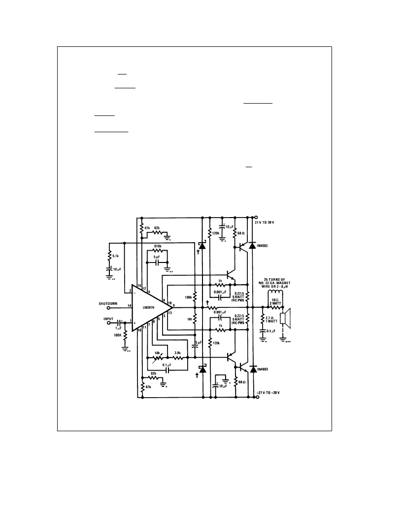
Typical Applications
(Continued)
40W-8
X
, 60W-4
X
Amplifier
*
High Frequency Ground
**
Input Ground
***
Speaker Ground
TL/H/7146–13
Note: All Grounds Should be Tied Together
Only at Power Supply Ground.
2
Additional protection for LM391N; Schottky diodes and R
j
100
X
.
11
相關PDF資料 |
PDF描述 |
|---|---|
| LM391 | LM391 Audio Power Driver |
| LM39301R-3.3 | 3A Low-Voltage Low-Dropout Regulator |
| LM393 | Dual Differential Comparators |
| LM193LB | Analog Comparator |
| LM2903DP | Low power dual voltage comparator |
相關代理商/技術參數 |
參數描述 |
|---|---|
| LM3914VX/NOPB | 功能描述:LED照明驅動器 DOT/BAR DISPLAY DRVR RoHS:否 制造商:STMicroelectronics 輸入電壓:11.5 V to 23 V 工作頻率: 最大電源電流:1.7 mA 輸出電流: 最大工作溫度: 安裝風格:SMD/SMT 封裝 / 箱體:SO-16N |
| LM3915 | 制造商:NSC 制造商全稱:National Semiconductor 功能描述:Dot/Bar Display Driver |
| LM3915J/A+ | 制造商:未知廠家 制造商全稱:未知廠家 功能描述:LED Display Driver |
| LM3915N | 制造商:Texas Instruments 功能描述: 制造商:Texas Instruments 功能描述:IC LED DISPLAY DRIVER 3915 DIP18 |
| LM3915N/A+ | 制造商:未知廠家 制造商全稱:未知廠家 功能描述:LED Display Driver |
發(fā)布緊急采購,3分鐘左右您將得到回復。