- 您現(xiàn)在的位置:買賣IC網(wǎng) > PDF目錄385474 > LM1209 (National Semiconductor Corporation) 130 MHz/100 MHz RGB Video Amplifier System with Blanking PDF資料下載
參數(shù)資料
| 型號: | LM1209 |
| 廠商: | National Semiconductor Corporation |
| 元件分類: | 運動控制電子 |
| 英文描述: | 130 MHz/100 MHz RGB Video Amplifier System with Blanking |
| 中文描述: | 130 MHz/100 MHz的RGB視頻信號放大器系統(tǒng)的沖裁 |
| 文件頁數(shù): | 20/25頁 |
| 文件大?。?/td> | 434K |
| 代理商: | LM1209 |
Applications of the LM1208/LM1209
(Continued)
the current during a voltage surge. A larger resistor is re-
quired because these inputs are DC coupled, allowing the
current to continuously flow into these inputs before the
monitor is turned on. 100
X
resistors are not recommended
at the video inputs because this resistance value will start to
roll off the frequency response of the LM1208/LM1209.
Note that the layout shown in Figure 16 does have a very
extensive ground plane. One must remember that the
LM1208/LM1209 is a 130 MHz/100 MHz part and a single
sided board is difficult to successfully design. A ground
plane similar to the layout shown in Figure 16 must be pro-
vided for good performance of the LM1208/LM1209 when
using either a single sided or double sided board. The layout
of this board demonstrates the importance of grounding.
The results of this layout are shown in Figures 17a through
17d. In these photographs the LM1208 rise time was
2.40 ns and the fall time was 3.00 ns. For the LM1209, the
rise time was 3.05 ns and the fall time was 3.45 ns. The
output was a 4 V
PP
signal and the cutoff voltage was set to
2V. The overshoot will subsequently be filtered out by the
loading effects of the CRT driver stage and the CRT itself.
When the LM1208/LM1209 is designed into a video board
one must keep the ground to the CRT driver stage separate
from the ground of the LM1208/LM1209, connecting the
two grounds together only at one point. National Semicon-
ductor also manufactures a line of CRT drivers. Please con-
tact National for additional information. These drivers great-
ly simplify the driver design allowing for shorter design cy-
cles. Of course the LM1208/LM1209 can also be designed
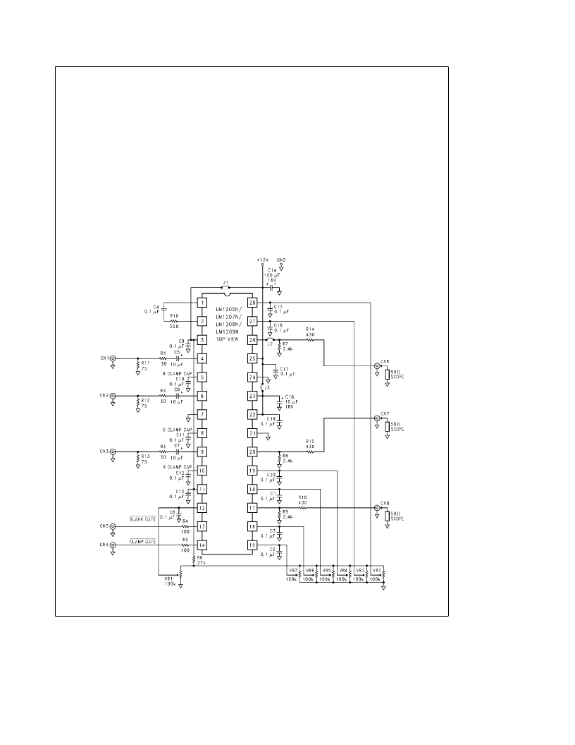
with a discrete driver stage.Figure 18 shows a design using
a simple cascode CRT driver. The LM1208/LM1209 block
would be the same schematic as shown in Figure 15.
REFERENCES
Zahid Rahim, ‘‘Guide to CRT Video Design,’’ Application
Note 861, National Semiconductor Corp., Jan. 1993
Ott, Henry W. Noise Reduction Techniques in Electronic
Systems, John Wiley & Sons, New York, 1976
TL/H/11884–20
FIGURE 15. Demonstration Board Schematic
http://www.national.com
20
相關(guān)PDF資料 |
PDF描述 |
|---|---|
| LM1212N | 230 MHz Video Amplifier System with OSD Blanking |
| LM1229 | I2C Compatible CMOS TV RGB and Deflection Processor |
| LM1229VEC | I2C Compatible CMOS TV RGB and Deflection Processor |
| LM1229YA | I2C Compatible CMOS TV RGB and Deflection Processor |
| LM1247 | 150 MHz I2C Compatible RGB Preamplifier with Internal 512 Character OSD ROM, 512 Character RAM and 4 DACs |
相關(guān)代理商/技術(shù)參數(shù) |
參數(shù)描述 |
|---|---|
| LM120A-05 | 制造商:SEME-LAB 制造商全稱:Seme LAB 功能描述:1.5 AMP NEGATIVE VOLTAGE REGULATOR |
| LM120AG-05 | 制造商:未知廠家 制造商全稱:未知廠家 功能描述:Analog IC |
| LM120AG-05-8QR-B | 制造商:未知廠家 制造商全稱:未知廠家 功能描述:Voltage Regulator |
| LM120AG-12 | 制造商:未知廠家 制造商全稱:未知廠家 功能描述:Voltage Regulator |
| LM120AG-12-8QR-B | 制造商:未知廠家 制造商全稱:未知廠家 功能描述:Voltage Regulator |
發(fā)布緊急采購,3分鐘左右您將得到回復(fù)。