- 您現(xiàn)在的位置:買賣IC網(wǎng) > PDF目錄30738 > LC89971M SPECIALTY CONSUMER CIRCUIT, PDSO24 PDF資料下載
參數(shù)資料
| 型號(hào): | LC89971M |
| 元件分類: | 消費(fèi)家電 |
| 英文描述: | SPECIALTY CONSUMER CIRCUIT, PDSO24 |
| 封裝: | MFP-24 |
| 文件頁(yè)數(shù): | 1/9頁(yè) |
| 文件大小: | 140K |
| 代理商: | LC89971M |

Ordering number : EN4900A
63095 TH (OT) No. 4900-1/9
Overview
The LC89971 and LC89971M are CCD delay lines for multi
television systems. They incorporate a comb filter for
chrominance signal and a 1H delay line for luminance
signal.
Structure
NMOS + CCD
Functions
Two CCD shift registers (for chrominance and
luminance signals)
CCD drive circuits
CCD stage count switching circuit
CCD signal adder
Auto-bias circuit
Sync tip clamping circuit (luminance signal)
Center-bias circuit (chrominance signal)
Sample-and-hold circuit
PLL 4
× frequency multiplier
fsc clock output circuit
RD voltage generator
Features
5 V single-voltage power supply
Built-in PLL 4
× frequency multiplier circuit allows
4 fsc operation from an fsc (3.58 MHz) input.
Control pin switchable to handle NTSC/M, PAL/GBI
and PAL/M systems.
Built-in chrominance signal crosstalk exclusion comb
filter features high precision comb characteristics in an
adjustment-free circuit.
Built-in peripheral circuits allow applications to be
constructed with a minimum number of external
components.
Positive-phase signal input/positive-phase signal output
(luminance signal)
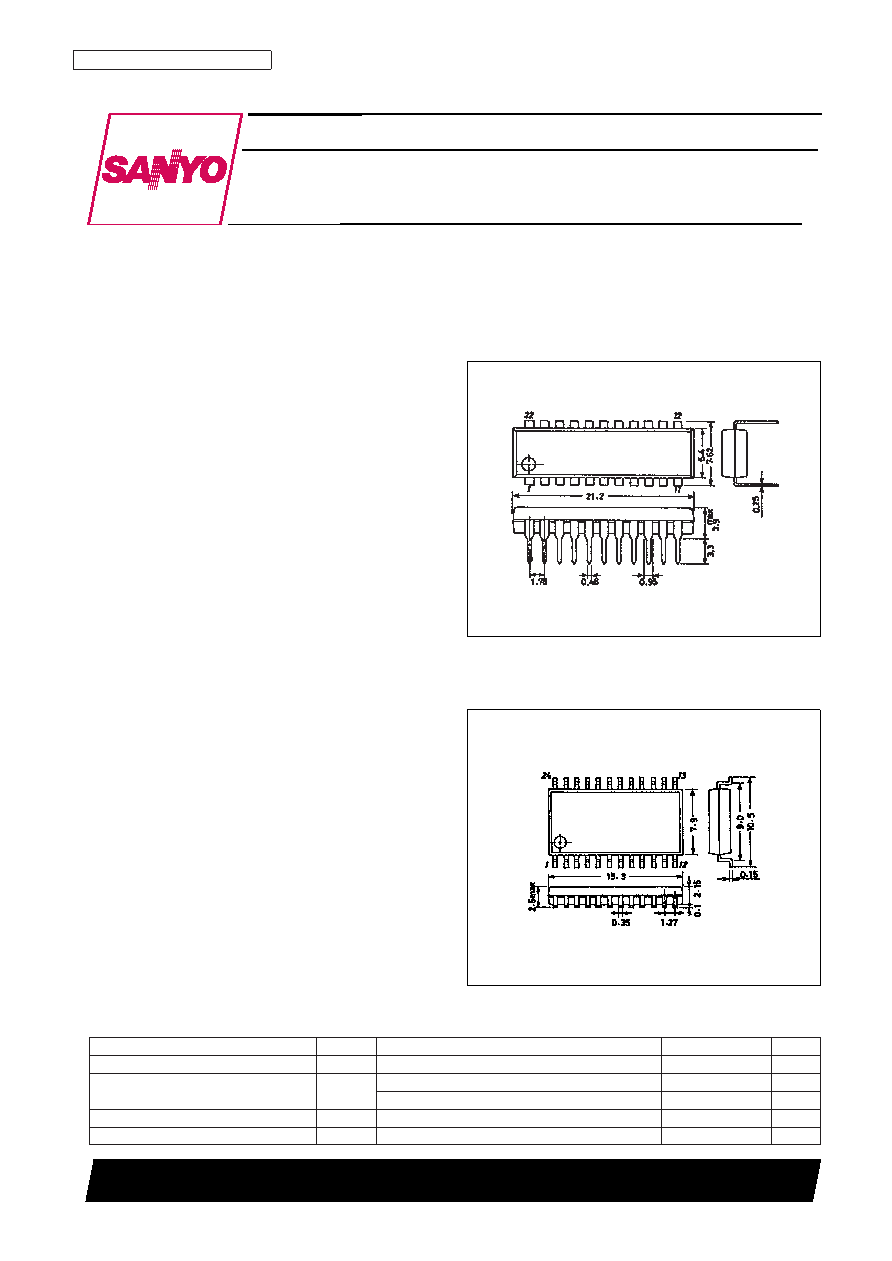
Package Dimensions
unit: mm
3059-DIP22S (375 mil)
unit: mm
3045B-MFP24
SANYO: DIP22S
[LC89971]
SANYO: MFP24
[LC89971M]
LC89971, 89971M
SANYO Electric Co.,Ltd. Semiconductor Bussiness Headquarters
TOKYO OFFICE Tokyo Bldg., 1-10, 1 Chome, Ueno, Taito-ku, TOKYO, 110-8534 JAPAN
Multi-system CCD Delay Line
MOS IC
Specifications
Absolute Maximum Ratings at Ta = 25°C
Parameter
Symbol
Conditions
Ratings
Unit
Maximum supply voltage
VDD max
–0.3 to +6.0
V
Allowable power dissipation
Pd max
LC89971
1200
mW
LC89971M
600
mW
Operating temperature
Topr
–10 to +70
°C
Storage temperature
Tstg
–55 to +150
°C
相關(guān)PDF資料 |
PDF描述 |
|---|---|
| LC89972M | SPECIALTY CONSUMER CIRCUIT, PDSO24 |
| LC89973M | SPECIALTY CONSUMER CIRCUIT, PDSO24 |
| LC89975M | SPECIALTY CONSUMER CIRCUIT, PDSO14 |
| LC89976 | SPECIALTY CONSUMER CIRCUIT, PDIP14 |
| LC89976M | SPECIALTY CONSUMER CIRCUIT, PDSO14 |
相關(guān)代理商/技術(shù)參數(shù) |
參數(shù)描述 |
|---|---|
| LC89972 | 制造商:SANYO 制造商全稱:Sanyo Semicon Device 功能描述:PAL CCD Delay Line |
| LC89972M | 制造商:SANYO 制造商全稱:Sanyo Semicon Device 功能描述:PAL CCD Delay Line |
| LC89973 | 制造商:未知廠家 制造商全稱:未知廠家 功能描述: |
| LC89973M | 制造商:SANYO 制造商全稱:Sanyo Semicon Device 功能描述:PAL CCD Delay Line |
| LC89975M | 制造商:SANYO 制造商全稱:Sanyo Semicon Device 功能描述:PAL-Format Delay Line |
發(fā)布緊急采購(gòu),3分鐘左右您將得到回復(fù)。