- 您現(xiàn)在的位置:買賣IC網(wǎng) > PDF目錄384585 > L6238SQT (意法半導(dǎo)體) 12V SENSORLESS SPINDLE MOTOR CONTROLLER PDF資料下載
參數(shù)資料
| 型號(hào): | L6238SQT |
| 廠商: | 意法半導(dǎo)體 |
| 英文描述: | 12V SENSORLESS SPINDLE MOTOR CONTROLLER |
| 中文描述: | 12V的無(wú)傳感器主軸電機(jī)控制器 |
| 文件頁(yè)數(shù): | 20/31頁(yè) |
| 文件大小: | 324K |
| 代理商: | L6238SQT |
第1頁(yè)第2頁(yè)第3頁(yè)第4頁(yè)第5頁(yè)第6頁(yè)第7頁(yè)第8頁(yè)第9頁(yè)第10頁(yè)第11頁(yè)第12頁(yè)第13頁(yè)第14頁(yè)第15頁(yè)第16頁(yè)第17頁(yè)第18頁(yè)第19頁(yè)當(dāng)前第20頁(yè)第21頁(yè)第22頁(yè)第23頁(yè)第24頁(yè)第25頁(yè)第26頁(yè)第27頁(yè)第28頁(yè)第29頁(yè)第30頁(yè)第31頁(yè)
given application is too slow. Figure 4-9 is an os-
cillograph taken on a device thathad a fairlylarge
value for Rslew and failed to spin up and phase
lock a motor.
The problem manifests itself as the motor begins
to spin up. At lower RPMs, the Bemf of the motor
is relatively small resulting in higher amounts of
commutation current. In figure 4-9, the upper
waveform is the voltage appearing at
OUTPUT
relative to the
CENTER TAP
input. The lower
waveform is the actual output of the Bemf ampli-
fier availableon specialengineering prototypes.
The oscillograph was taken just as the problem
occured. The period between zero crossings was
~800
μ
s resulting in a masktime period of 200
μ
s.
As can be seen, the excessively long slew rate
actually exceeded the mask period and was de-
tected as a zero crossing.
This resulted in improper sequencing of the out-
putsrelative to the proper phases and causedthe
motor to spindown.
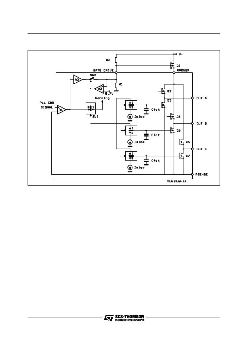
4.7 Ext PFET Driver
The power handling capabilities of the 3 phase
output stage can be extended with the addition of
a single P-ChannelFET.
Figure 4-10 shows the Ext FET connection and
demonstrates how the L6238S automatically
senses the FETs presence. When the voltage at
the
Gate Drive
pin is
≥
0.7V, the output of com-
parator A3 goes high, removing the variable drive
A1 from the internal FETs and connects them in-
stead to Vanalogvia the commutation switches to
facilitate full conduction.
The upper FETs drive paths are not shown for
clarity. A3 also closes SW2 allowing A1 to linearly
drive the external P-Channel FET Q1 via inverter
A2.
4.8 Bemf Ampolifier
Since no Hall Effect Sensors are required, the
commutation information is derivedfrom the Bemf
voltage zero-crossings of the undriven phase with
respect to the center tap. The Bemf comparator
and associatedsignal levels are depictedin figure
4-11. For reliable operation, the Bemf signal am-
plitude should be a minimum of
±
60 mV to be
properly detected. In order to provide for noise
immunity, internal hysteresis is incorporated in
the detection circuitry to prevent false zero cross-
ing detection.
For laboratory evaluation purposes, a simple re-
Figure 4-10:
ExternalP-Fet.
L6238S
20/31
相關(guān)PDF資料 |
PDF描述 |
|---|---|
| L6327 | 6 / 4 CHANNEL VOLTAGE SENSE GMR PREAMPLIFIER |
| L6332 | 6 / 4 CHANNEL VOLTAGE SENSE GMR PREAMPLIFIER |
| L6353D | SMART DRIVER FOR POWER MOS & IGBT |
| L6363 | PRML READ/WRITE CHANNEL |
| L6377D | 0.5A HIGH-SIDE DRIVER INTELLIGENT POWER SWITCH |
相關(guān)代理商/技術(shù)參數(shù) |
參數(shù)描述 |
|---|---|
| L6239 | 制造商:未知廠家 制造商全稱:未知廠家 功能描述: |
| L623C | 制造商:未知廠家 制造商全稱:未知廠家 功能描述:THYRISTOR MODULE|BRIDGE|HALF-CNTLD|CA|280V V(RRM)|46A I(T) |
| L623F | 制造商:未知廠家 制造商全稱:未知廠家 功能描述:THYRISTOR MODULE|BRIDGE|HALF-CNTLD|CA|280V V(RRM)|46A I(T) |
| L624 | 制造商:CRYDOM 制造商全稱:Crydom Inc., 功能描述:Power Modules |
| L6242 | 制造商:STMICROELECTRONICS 制造商全稱:STMicroelectronics 功能描述:VOICE COIL MOTOR DRIVER |
發(fā)布緊急采購(gòu),3分鐘左右您將得到回復(fù)。