- 您現(xiàn)在的位置:買賣IC網(wǎng) > PDF目錄97995 > L6238SQA (STMICROELECTRONICS) BRUSHLESS DC MOTOR CONTROLLER, 5 A, PQFP44 PDF資料下載
參數(shù)資料
| 型號: | L6238SQA |
| 廠商: | STMICROELECTRONICS |
| 元件分類: | 運(yùn)動控制電子 |
| 英文描述: | BRUSHLESS DC MOTOR CONTROLLER, 5 A, PQFP44 |
| 封裝: | PLASTIC, QFP-44 |
| 文件頁數(shù): | 4/31頁 |
| 文件大小: | 3465K |
| 代理商: | L6238SQA |
第1頁第2頁第3頁當(dāng)前第4頁第5頁第6頁第7頁第8頁第9頁第10頁第11頁第12頁第13頁第14頁第15頁第16頁第17頁第18頁第19頁第20頁第21頁第22頁第23頁第24頁第25頁第26頁第27頁第28頁第29頁第30頁第31頁
If zero crossings are detected, the sequencer will
automatically lock on to the proper phase.
This resynchronization will take effect with the
motor speed running as low as typically 30% of
it’s nominal value.
2.5 External Sequencing
Although the user-defined Start-Up Algorithm is
flexible and will consistently spin up a motor with
no external interaction, the possibility exists
where certain applications might require complete
microprocessor control of start-up.
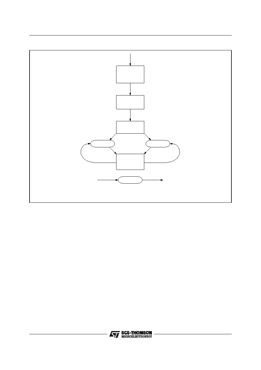
The L6238S offers this capability via the SE-
QUENCE INCREMENT input. Referring to figure
2-5, during initial power-up with Output Enable
low, the controller is in the "Hold and Wait for De-
cision" state. If the SEQUENCE INCREMENT pin
is brought high during this state, the Auto StartUp
Algorithm is disabled and the sequencer can be
controlled externally.
When Output
Enable and
Run/Brake
are
brought high, the sequencer is incremented on
each positive transition o the SEQUENCER IN-
CREMENT pin. During the time that this pin is
high, all Bemf information is masked out. When it
is low, the Bemf information can be detected nor-
mally after the internal mask time. The minimum
mask time is 192/Sys_Clk (i.e. with Sys_Clk =
10MHz, min. mask = 19.2
s) Therefore to insure
that the sequencer is under complete control of
the state machine, the time that the SEQUENCE
INCREMENT pin is held low should be much less
then the min. mask time, but greater then 1
s.
When the motor has reached a predetermined
speed, the SEQUENCE INCREMENT pin can be
left low and the L6238S Motor Control logic will
take over and automatically spin up the motor to
the desired speed
.
3.0 START-UP ALGORITHMS
3.1 Spin-Up Operation
The spin operation can be separated into 3 parts:
1) Open Loop Start-Up - The object is to create
motion in the desired direction so that the Bemf
voltages at the 3 motor terminals can provide reli-
able information enabling a transition to closed
loop operation.
STATE=1
DRIVERS OFF
MIN CLOCK DELAY
PERIOD STOP
DELAY STOP
MASK STOP
INT START-UP DISABLED
MIN CLOCK DELAY
LOAD MIN DELAY
LOAD MIN MASK
MASK COUNT
SEQINC=1 &
OUTENA=0
RUN/BRK=X
D95IN313
*VALID IF SEQINC=0, AND DELAY TIMES OUT
**CLOCK DELAY=F(TDLY_[2:0])
WHEN BEMF PERIOD <3.3ms @ 10MHz (SPEED >12.7Hz FOR 8 POLES)
SEQINC=0
STATE=STATE+1
MASK COUNT
LOAD DELAY=PERIOD
LOAD MASK=PERIOD
RESET PERIOD
PERIOD COUNT
DELAY COUNT**
BEMF
POR=0
FROM ANY STATE
DRIVERS ON
PERIOD COUNT
DELAY COUNT
SEQINC=0
BEMF
SEQINC=1
STATE=STATE+1
SEQINC=1
FROM ANY STATE
WITH SEQ_INC=0
RETURN TO
PREVIOUS STATE
(CHANGING SEQINC=1)
RUN/BRK=1 &
OUTENA=1
SEQINC=1
Figure 2-5
L6238S
12/31
相關(guān)PDF資料 |
PDF描述 |
|---|---|
| L6238SQT | BRUSHLESS DC MOTOR CONTROLLER, 5 A, PQFP64 |
| L6238S013TR | BRUSHLESS DC MOTOR CONTROLLER, 5 A, PQCC44 |
| L6246 | VOICE COIL MOTOR CONTROLLER, 3 A, PQFP44 |
| L6258EA | STEPPER MOTOR CONTROLLER, 2 A, PDSO36 |
| L6268 | VOICE COIL MOTOR CONTROLLER, 2.1 A, PQFP44 |
相關(guān)代理商/技術(shù)參數(shù) |
參數(shù)描述 |
|---|---|
| L6238SQT | 制造商:STMICROELECTRONICS 制造商全稱:STMicroelectronics 功能描述:12V SENSORLESS SPINDLE MOTOR CONTROLLER |
| L6239 | 制造商:未知廠家 制造商全稱:未知廠家 功能描述: |
| L623C | 制造商:未知廠家 制造商全稱:未知廠家 功能描述:THYRISTOR MODULE|BRIDGE|HALF-CNTLD|CA|280V V(RRM)|46A I(T) |
| L623F | 制造商:未知廠家 制造商全稱:未知廠家 功能描述:THYRISTOR MODULE|BRIDGE|HALF-CNTLD|CA|280V V(RRM)|46A I(T) |
| L624 | 制造商:CRYDOM 制造商全稱:Crydom Inc., 功能描述:Power Modules |
發(fā)布緊急采購,3分鐘左右您將得到回復(fù)。