- 您現(xiàn)在的位置:買賣IC網(wǎng) > PDF目錄373176 > KS0108B (SAMSUNG SEMICONDUCTOR CO. LTD.) Dot matrix LCD Driver(點陣LCD的驅(qū)動器) PDF資料下載
參數(shù)資料
| 型號: | KS0108B |
| 廠商: | SAMSUNG SEMICONDUCTOR CO. LTD. |
| 英文描述: | Dot matrix LCD Driver(點陣LCD的驅(qū)動器) |
| 中文描述: | 點陣LCD驅(qū)動器(點陣液晶顯示的驅(qū)動器) |
| 文件頁數(shù): | 20/26頁 |
| 文件大?。?/td> | 227K |
| 代理商: | KS0108B |
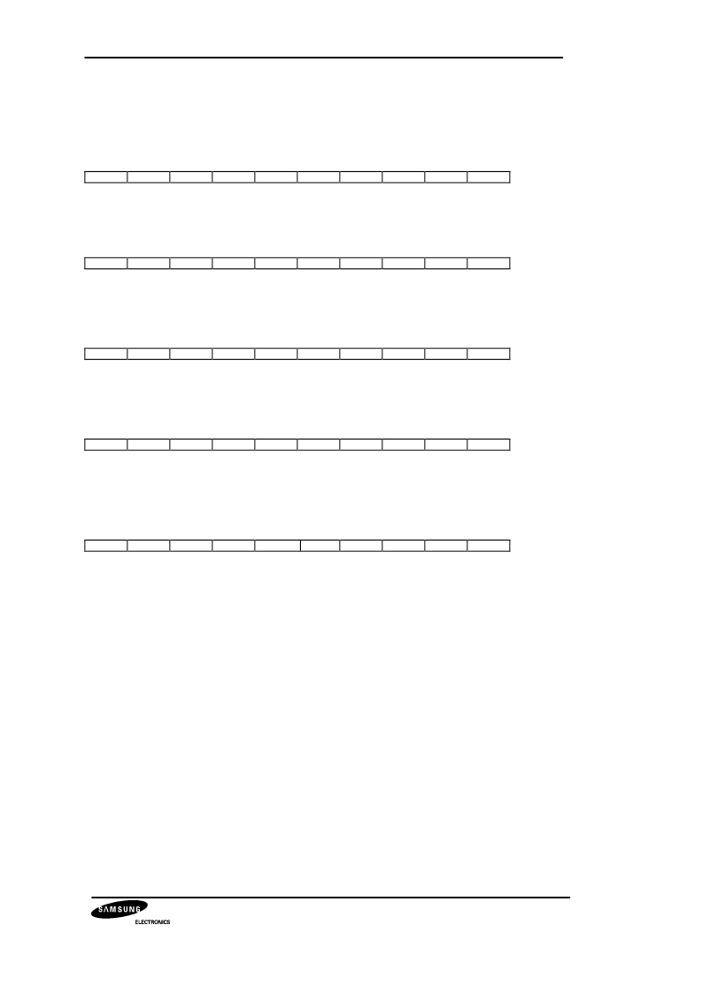
KS0108B 64CH SEGMENT DRIVER FOR DOT MATRIX LCD
1. Display On/Off
RS
R/W DB7 DB6 DB5 DB4 DB3 DB2 DB1 DB0
0
0
0
1
0
1
1
1
1
D
The display data appears when D is 1 and disappears when D is 0.
Though the data is not on the screen with D=0, it remains in the display data RAM.
Therefore, you can make it appear by changing D=0 into D=1.
2. Set Address (Y Address)
S
R/W DB7 DB6 DB5 DB4 DB3 DB2 DB1 DB0
0
0
0
1
AC5
AC4
AC3
AC2
AC1
AC0
Y address (AC0 ~ AC5) of the display data RAM is set in the Y address counter.
An address is set by instruction and increased by 1 automatically by read or write operations
of display data.
3. Set Page (X Address)
RS
R/W DB7 DB6 DB5 DB4 DB3 DB2 DB1 DB0
0
0
1
0
1
1
1
AC2
AC1
AC0
X address(AC0 ~ AC2) of the display data RAM is set in the X address register.
Writing or reading to or from MPU is executed in this specified page until the next page
is set.
4. Display Start Line (Z Address)
RS
R/W DB7 DB6 DB5 DB4 DB3 DB2 DB1 DB0
0
0
1
1
AC5
AC4
AC3
AC2
AC1
AC0
Z address (AC0 ~ AC5) of the display data RAM is set in the display start line register and
displayed at the top of the screen.
When the display duty cycle is 1/64 or others(1/32 ~ 1/64), the data of total line number of
LCD screen, from the line specified by display start line instruction, is displayed.
5. Status Read
RS
1
R/W DB7 DB6 DB5 DB4 DB3 DB2 DB1 DB0
0
BUSY
0
ON/OFF
RESET
0
0
0
0
l
BUSY
When BUSY is 1, the Chip is executing internal operation and no instructions are accepted.
When BUSY is 0, the Chip is ready to accept any instructions.
ON/OFF
When ON/OFF is 1, the display is on.
When ON/OFF is 0, the display is off.
RESET
When RESET is 1, the system is being initialized.
In this condition, no instructions except status read can be accepted.
When RESET is 0, initializing has finished and the system is in the usual operation condition.
l
l
相關(guān)PDF資料 |
PDF描述 |
|---|---|
| KS0118C | GENLOCK ADC(采樣時鐘鎖定的視頻/數(shù)字轉(zhuǎn)換器) |
| KS0119 | Multimedia Video(帶傳統(tǒng)RAM-DAC功能的NTSC編碼器) |
| KS0122 | MULTISTANDARD VIDEO DECODER |
| KS0123 | DIGITAL VIDEO ENCODER |
| KS0125 | Multi-standard Video Encoder(多標準視頻編碼器) |
相關(guān)代理商/技術(shù)參數(shù) |
參數(shù)描述 |
|---|---|
| KS0118C | 制造商:SAMSUNG 制造商全稱:Samsung semiconductor 功能描述:GENLOCK ADC |
| KS0122 | 制造商:SAMSUNG 制造商全稱:Samsung semiconductor 功能描述:MULTISTANDARD VIDEO DECODER |
| KS0123 | 制造商:SAMSUNG 制造商全稱:Samsung semiconductor 功能描述:DIGITAL VIDEO ENCODER |
| KS0127 | 制造商:Samsung SDI 功能描述:Digital video encoder & decoder |
| KS0127B | 制造商:SAMSUNG 制造商全稱:Samsung semiconductor 功能描述:MULTISTANDARD VIDEO DECODER/SCALER |
發(fā)布緊急采購,3分鐘左右您將得到回復(fù)。