- 您現(xiàn)在的位置:買賣IC網(wǎng) > PDF目錄385408 > HT95CXXX (Holtek Semiconductor Inc.) CID Type Phone 8-Bit MCU PDF資料下載
參數(shù)資料
| 型號: | HT95CXXX |
| 廠商: | Holtek Semiconductor Inc. |
| 英文描述: | CID Type Phone 8-Bit MCU |
| 中文描述: | 刑事偵緝式電話8位微控制器 |
| 文件頁數(shù): | 6/51頁 |
| 文件大?。?/td> | 384K |
| 代理商: | HT95CXXX |
第1頁第2頁第3頁第4頁第5頁當(dāng)前第6頁第7頁第8頁第9頁第10頁第11頁第12頁第13頁第14頁第15頁第16頁第17頁第18頁第19頁第20頁第21頁第22頁第23頁第24頁第25頁第26頁第27頁第28頁第29頁第30頁第31頁第32頁第33頁第34頁第35頁第36頁第37頁第38頁第39頁第40頁第41頁第42頁第43頁第44頁第45頁第46頁第47頁第48頁第49頁第50頁第51頁

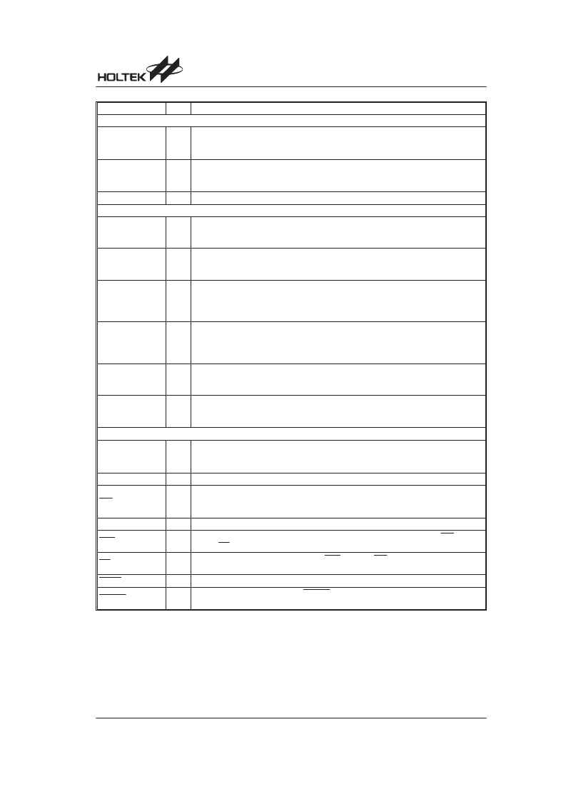
Pin Name
I/O
Description
LCD Driver
SEG47~SEG0
O
or
I/O
LCD panel segment outputs.
Some segment outputs can be optioned to Bidirectional input/output ports by software.
(See the LCD Driver function)
COM15~COM0
O
or
I/O
LCD panel common outputs.
Some common outputs can be optioned to Bidirectional input/output ports by software.
(See the LCD Driver function)
VLCD
I
LCD driver power source.
Normal I/O
PA7~PA0
I/O
Bidirectional input/output ports.
Schmitt trigger input and CMOS output.
See mask option table for pull-high and wake-up function
PB7~PB0
I/O
Bidirectional input/output ports.
Schmitt trigger input and CMOS output.
See mask option table for pull-high function
PD7~PD0
I/O
Bidirectional input/output ports.
Schmitt trigger input and CMOS output.
See mask option table for pull-high function
Port D could be optioned to LCD signal output, see the Input/Output Ports function
PE3~PE0
I/O
Bidirectional input/output ports.
Schmitt trigger input and CMOS output.
See mask option table for pull-high function
Port E could be optioned to LCD signal output, see the Input/Output Ports function
PF7~PF0
I/O
Bidirectional input/output ports.
Schmitt trigger input and CMOS output.
See mask option table for pull-high function
PG3~PG0
I/O
Bidirectional input/output ports.
Schmitt trigger input and CMOS output.
See mask option table for pull-high function
Dialer I/O (See the Dialer I/O function )
HFI
I
Schmitt trigger input structure. An external RC network is recommended for input
debouncing.
This pin is pulled low with internal resistance of 200k
typ.
HFO
O
CMOS output structure.
HDI
I
Schmitt trigger input structure. An external RC network is recommended for input
debouncing.
This pin is pulled high with internal resistance of 200k
typ.
HDO
O
CMOS output structure.
HKS
I
This pin detects the status of the hook-switch and its combination with HFI/HDI can con-
trol the PO pin output to make or break the line.
PO
O
CMOS output structure controlled by HKS and HFI/HDI pins and which determines
whether the dialer connects or disconnects the telephone line.
DNPO
O
NMOS output structure.
XMUTE
O
NMOS output structure. Usually, XMUTE is used to mute the speech circuit when trans-
mitting the dialer signal.
HT95CXXX
Rev. 1.50
6
May 26, 2005
相關(guān)PDF資料 |
PDF描述 |
|---|---|
| HT95L400-128QFP-A | LCD Type Phone 8-Bit MCU |
| HT95L100-64QEP-A | LCD Type Phone 8-Bit MCU |
| HT95L10P-64QEP-A | LCD Type Phone 8-Bit MCU |
| HT95L100-64QFP-A | 8-Bit LCD Type Phone Controller MCU |
| HT95L10P-64QFP-A | 8-Bit LCD Type Phone Controller MCU |
相關(guān)代理商/技術(shù)參數(shù) |
參數(shù)描述 |
|---|---|
| HT95L000 | 制造商:HOLTEK 制造商全稱:Holtek Semiconductor Inc 功能描述:CID Type Phone 8-Bit MCU |
| HT95L000-56SSOP-A | 制造商:HOLTEK 制造商全稱:Holtek Semiconductor Inc 功能描述:LCD Type Phone 8-Bit MCU |
| HT95L00P | 制造商:HOLTEK 制造商全稱:Holtek Semiconductor Inc 功能描述:LCD Type Phone 8-Bit MCU |
| HT95L00P-56SSOP-A | 制造商:HOLTEK 制造商全稱:Holtek Semiconductor Inc 功能描述:LCD Type Phone 8-Bit MCU |
| HT95L100 | 制造商:HOLTEK 制造商全稱:Holtek Semiconductor Inc 功能描述:CID Type Phone 8-Bit MCU |
發(fā)布緊急采購,3分鐘左右您將得到回復(fù)。