- 您現(xiàn)在的位置:買賣IC網(wǎng) > PDF目錄385407 > HT95A200 (Holtek Semiconductor Inc.) I/O Type Phone 8-Bit MCU PDF資料下載
參數(shù)資料
| 型號(hào): | HT95A200 |
| 廠商: | Holtek Semiconductor Inc. |
| 英文描述: | I/O Type Phone 8-Bit MCU |
| 中文描述: | I / O型電話8位微控制器 |
| 文件頁(yè)數(shù): | 12/48頁(yè) |
| 文件大小: | 360K |
| 代理商: | HT95A200 |
第1頁(yè)第2頁(yè)第3頁(yè)第4頁(yè)第5頁(yè)第6頁(yè)第7頁(yè)第8頁(yè)第9頁(yè)第10頁(yè)第11頁(yè)當(dāng)前第12頁(yè)第13頁(yè)第14頁(yè)第15頁(yè)第16頁(yè)第17頁(yè)第18頁(yè)第19頁(yè)第20頁(yè)第21頁(yè)第22頁(yè)第23頁(yè)第24頁(yè)第25頁(yè)第26頁(yè)第27頁(yè)第28頁(yè)第29頁(yè)第30頁(yè)第31頁(yè)第32頁(yè)第33頁(yè)第34頁(yè)第35頁(yè)第36頁(yè)第37頁(yè)第38頁(yè)第39頁(yè)第40頁(yè)第41頁(yè)第42頁(yè)第43頁(yè)第44頁(yè)第45頁(yè)第46頁(yè)第47頁(yè)第48頁(yè)

HT95AXXX
Rev. 1.20
12
May 26, 2004
If the stack is full, any other interrupt request will not be
acknowledged, even if the related interrupt is enabled,
until the stack pointer is decremented. If immediate ser-
vice is desired, the stack must be prevented from be-
coming full.
All these kinds of interrupts have a wake-up capability.
As an interrupt is serviced, a control transfer occurs by
pushing the program counter onto the stack, followed by
a branch to a subroutine at specified location in the pro-
gram memory. Only the program counter is pushed onto
the stack. If the contents of the register or status register
(STATUS) are altered by the interrupt service program
which corrupts the desired control sequence, the con-
tents should be saved in advance.
External interrupt is triggered by a high to low transition
of the INT pin (HT95A400/40P,HT95A300/30P,
HT95A200/20P) or INT/TMR0 (HT95A100/10P) and the
interrupt request flag EIF will be set. When the external
interrupt is enabled, the stack is not full and the external
interrupt is active, a subroutine call to location 04H will
occur. The interrupt request flag EIF and EMI bits will be
cleared to disable other interrupts.
The Timer/Event Counter 0 interrupt is generated by a
timeout overflow and the interrupt request flag T0F will
be set. When the Timer/Event Counter 0 interrupt is en-
abled, the stack is not full and the T0F bit is set, a sub-
routine call to location 08H will occur. The interrupt
request flag T0F and EMI bits will be cleared to disable
further interrupts.
The Timer/Event Counter 1 interrupt is generated by a
timeout overflow and the interrupt request flag T1F will
be set. When the Timer/Event Counter 1 interrupt is en-
abled, the stack is not full and the T1F bit is set, a
subroutine call to location 0CH will occur. The interrupt
request flag T1F and EMI bits will be cleared to disable
further interrupts.
The real time clock interrupt is generated by a 1Hz RTC
generator. When the RTC time-out occurs, the interrupt
request flag RTCF will be set. When the RTC interrupt is
enabled, the stack is not full and the RTCF is set, a sub-
routine call to location 14H will occur. The interrupt re-
quest flag RTCF and EMI bits will be cleared to disable
other interrupts.
The dialer I/O interrupt is triggered by any edge transi-
tion onto HKS pin or a falling edge transition onto HDI
pin or a rising edge transition onto HFI pin, the interrupt
request flag DRF will be set. When the dialer I/O inter-
rupt is enabled, the stack is not full and the DRF is set, a
subroutine call to location 18H will occur. The interrupt
request flag DRF and EMI bits will be cleared to disable
other interrupts.
Note: 1. If the dialer status is on-hook and hold-line,
thefallingedgetransitionontoHDIpinwillnot
generate the dialer I/O interrupt.
2.TheHDIinputissupportedforHT95A400/40P,
HT95A300/30P and HT95A200/20P.
3. The dialer I/O interrupt will be disabled when
the operation mode is in Idle mode.
During the execution of an interrupt subroutine, other in-
terrupt acknowledge signals are held until the RETI in-
struction is executed or the EMI bit and the related
interrupt control bit are set to 1 (if the stack is not full). To
return from the interrupt subroutine, RET or RETI
may be invoked. RETI will set the EMI bit to enable an
interrupt service, but RET will not.
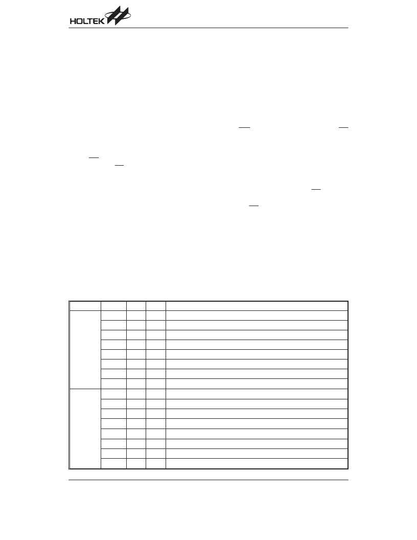
Register
Bits
Label
R/W
Function
INTC0
(0BH)
0
EMI
RW
Controls the master (global) interrupt (1=enabled; 0=disabled)
1
EEI
RW
Controls the external interrupt (1=enabled; 0=disabled)
2
ET0I
RW
Controls the Timer/Event Counter 0 interrupt (1=enabled; 0=disabled)
3
ET1I
RW
Controls the Timer/Event Counter 1 interrupt (1=enabled; 0=disabled)
4
EIF
RW
External interrupt request flag (1=active; 0=inactive)
5
T0F
RW
Timer/Event Counter 0 request flag (1=active; 0=inactive)
6
T1F
RW
Timer/Event Counter 1 request flag (1=active; 0=inactive)
7
RO
Unused bit, read as 0
INTC1
(1EH)
0
RW
Reserved, inhibit using
1
ERTCI
RW
Control the real time clock interrupt (1=enable; 0=disable)
2
EDRI
RW
Control the dialer I/O interrupt (1=enable; 0=disable)
3
RO
Unused bit, read as 0
4
RW
Reserved, inhibit using
5
RTCF
RW
Internal real time clock interrupt request flag (1=active; 0=inactive)
6
DRF
RW
Internal dialer I/O interrupt request flag (1=active: 0=inactive)
7
RO
Unused bit, read as 0
相關(guān)PDF資料 |
PDF描述 |
|---|---|
| HT95A300 | I/O Type Phone 8-Bit MCU |
| HT95AXXX | I/O Type Phone 8-Bit MCU |
| HT95C20P | 8-Bit CID Type Phone Controller MCU |
| HT95C300 | 8-Bit CID Type Phone Controller MCU |
| HT95C30P | 8-Bit CID Type Phone Controller MCU |
相關(guān)代理商/技術(shù)參數(shù) |
參數(shù)描述 |
|---|---|
| HT95A200/20P | 制造商:HOLTEK 制造商全稱:Holtek Semiconductor Inc 功能描述:I/O Type Phone 8-Bit MCU |
| HT95A20P | 制造商:HOLTEK 制造商全稱:Holtek Semiconductor Inc 功能描述:CID Type Phone 8-Bit MCU |
| HT95A300 | 制造商:HOLTEK 制造商全稱:Holtek Semiconductor Inc 功能描述:I/O Type Phone 8-Bit MCU |
| HT95A300/30P | 制造商:HOLTEK 制造商全稱:Holtek Semiconductor Inc 功能描述:I/O Type Phone 8-Bit MCU |
| HT95A30P | 制造商:HOLTEK 制造商全稱:Holtek Semiconductor Inc 功能描述:CID Type Phone 8-Bit MCU |
發(fā)布緊急采購(gòu),3分鐘左右您將得到回復(fù)。