- 您現(xiàn)在的位置:買賣IC網(wǎng) > PDF目錄385405 > HT86R192 (Holtek Semiconductor Inc.) Voice Synthesizer 8-Bit OTP MCU PDF資料下載
參數(shù)資料
| 型號(hào): | HT86R192 |
| 廠商: | Holtek Semiconductor Inc. |
| 英文描述: | Voice Synthesizer 8-Bit OTP MCU |
| 中文描述: | 語音合成器8位微控制器檢察官辦公室 |
| 文件頁數(shù): | 5/44頁 |
| 文件大?。?/td> | 287K |
| 代理商: | HT86R192 |
第1頁第2頁第3頁第4頁當(dāng)前第5頁第6頁第7頁第8頁第9頁第10頁第11頁第12頁第13頁第14頁第15頁第16頁第17頁第18頁第19頁第20頁第21頁第22頁第23頁第24頁第25頁第26頁第27頁第28頁第29頁第30頁第31頁第32頁第33頁第34頁第35頁第36頁第37頁第38頁第39頁第40頁第41頁第42頁第43頁第44頁

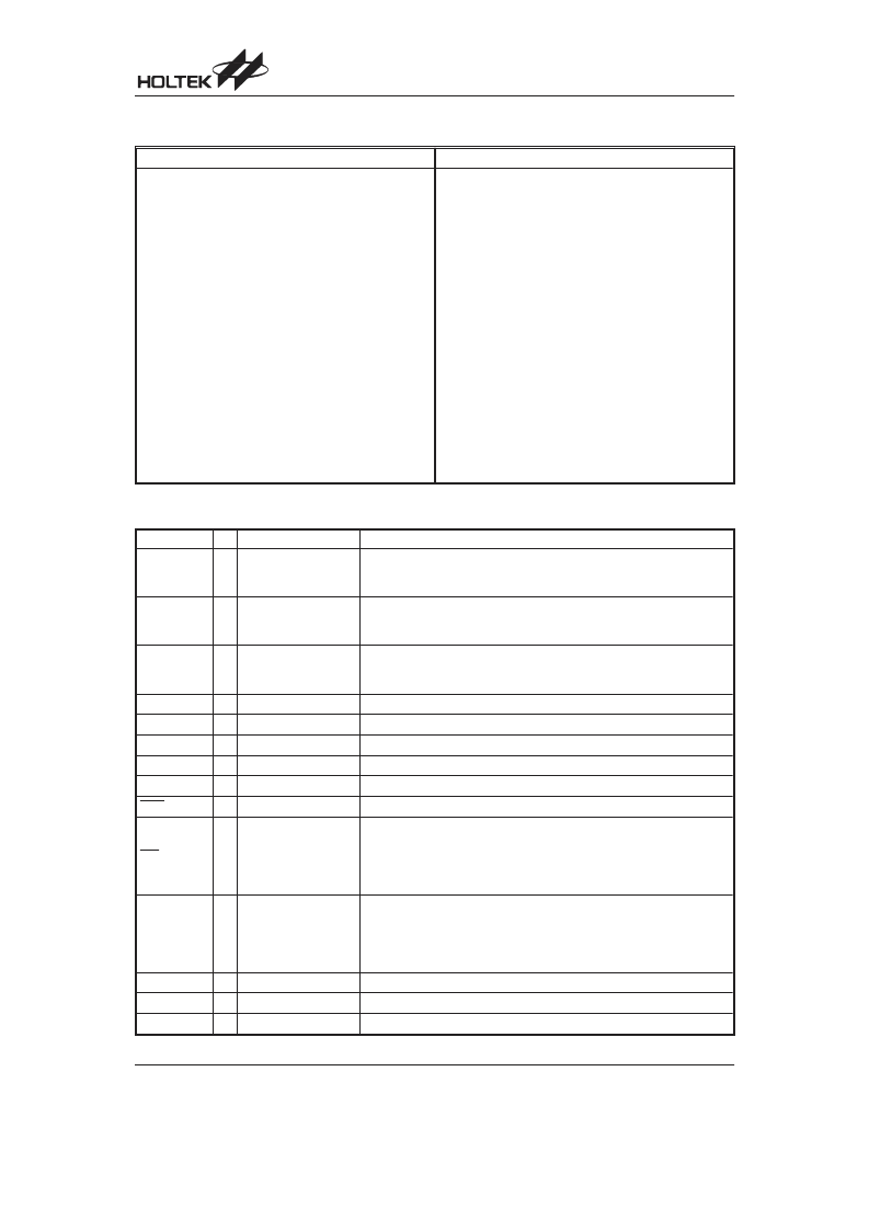
Pad Coordinates
Unit: m
Pad No.
X
Y
Pad No.
X
Y
1
2
3
4
5
6
7
8
9
1990.600
1990.600
1990.600
1990.600
1990.600
1990.600
1990.600
1990.600
1990.600
1990.600
1990.600
1784.650
1679.350
1576.350
1481.350
1378.350
1283.350
1180.350
1085.350
1465.900
1568.900
1663.900
1766.900
1861.900
1964.900
2059.900
2162.900
2257.900
2360.900
2455.900
2453.400
2453.400
2453.400
2453.400
2453.400
2453.400
2453.400
2453.400
20
21
22
23
24
25
26
27
28
29
30
31
32
33
34
35
36
37
982.350
887.350
784.350
689.350
586.350
454.800
364.800
274.800
23.900
81.110
186.100
291.100
397.100
508.900
1984.750
1990.900
1990.850
1990.850
2453.400
2453.400
2453.400
2453.400
2453.400
2467.000
2467.000
2467.000
2414.250
2399.950
2390.750
2384.950
2384.000
2384.000
2404.700
2232.500
2119.776
2016.174
10
11
12
13
14
15
16
17
18
19
Pad Description
Pad Name
I/O
OTP Option
Description
PA0~PA7
I/O
Wake-up,
Pull-high
or None
Bidirectional 8-bit I/O port. Each bit can be configured as a wake-up input
by OTP option. Software instructions determine the CMOS output or
Schmitt trigger input with or without pull-high resistor (OTP option).
PB0~PB7
I/O
Pull-high
or None
Bidirectional 8-bit I/O port. Software instructions determine the CMOS
output or Schmitt trigger input (pull-high resistor depending on OTP op-
tion).
PC0~PC5
PC6/XIN
I/O
Pull-high
or None
Bidirectional 7-bit I/O port. Software instructions determine the CMOS
output or Schmitt trigger input (pull-high resistor depending on OTP op-
tion). XIN is pin-shared with PC6
XOUT
32kHz RTC
Connected an external 32kHz crystal to XIN and XOUT.
VSS
Negative power supply, ground
VDD
Positive power supply
VDDA
DAC power supply
VSSA
DAC negative power supply, ground
RES
I
Schmitt trigger reset input, active low
INT
I
Falling Edge Trigger
or Falling/Rising Edge
Trigger
External interrupt Schmitt trigger input without pull-high resistor. Choice
falling edge trigger or falling/rising edge trigger by OTP option. Falling
edge triggered active on a high to low transition. Rising edge triggered
active on a low to high transition. Input voltage is the same as operating
voltage.
OSC1
OSC2
RC or Crystal
OSC1 and OSC2 are connected to an RC network or a crystal (by OTP
option) for the internal system clock. In the case of RC operation, OSC2
is the output terminal for 1/4 system clock.
The system clock may come from the crystal, the two pins cannot be
floating.
AUD
O
Audio output for driving a external transistor or for driving HT82V733
NC
No connection
TEST
No connection (open)
HT86R192
Rev. 0.00
5
October 23, 2006
Preliminary
相關(guān)PDF資料 |
PDF描述 |
|---|---|
| HT86R384 | Voice Synthesizer 8-Bit OTP MCU |
| HT86XXX | 8-Bit Voice Synthesizer MCU |
| HT8950 | Voice Modulator |
| HT8955 | Voice Echo |
| HT8955A | Voice Echo |
相關(guān)代理商/技術(shù)參數(shù) |
參數(shù)描述 |
|---|---|
| HT86R384 | 制造商:HOLTEK 制造商全稱:Holtek Semiconductor Inc 功能描述:Voice Synthesizer 8-Bit OTP MCU |
| HT86XXX | 制造商:HOLTEK 制造商全稱:Holtek Semiconductor Inc 功能描述:Voice Synthesizer 8-Bit MCU |
| HT86XXX_07 | 制造商:HOLTEK 制造商全稱:Holtek Semiconductor Inc 功能描述:Voice Synthesizer 8-Bit MCU |
| HT-87 | 制造商:Atlas Sound 功能描述:8W Speaker Line Matching Transformer |
| HT-8709 KIT | 制造商:UNBRANDED 功能描述:THERMO-HYGROMETER KIT |
發(fā)布緊急采購,3分鐘左右您將得到回復(fù)。