- 您現(xiàn)在的位置:買賣IC網(wǎng) > PDF目錄385401 > HT6750A (Holtek Semiconductor Inc.) Date Printer PDF資料下載
參數(shù)資料
| 型號: | HT6750A |
| 廠商: | Holtek Semiconductor Inc. |
| 英文描述: | Date Printer |
| 中文描述: | 日期打印機(jī) |
| 文件頁數(shù): | 5/8頁 |
| 文件大?。?/td> | 126K |
| 代理商: | HT6750A |

HT6750A
Rev. 1.00
5
January 17, 2003
Functional Description
6-digit timer in 5 modes: Mode selection for 3 key
applications
Date from 1-1- 98 to 31-12- 49 (2049) automatic
updating, including leap years.
Matrix address LCD interface in 1/3 duty, 1/2 bias,
frame frequency is 43Hz.
Printing enable is Go low trigger in X input. V
X
V
DD
,Debounceinprintingtrigger:1ms T
DEBOUNCE
2ms.
1/2
After printing,
will blink 3 times at 1Hz rate.
Print means lamp output LOW to light lamp. Lamp
output sink current is 40mA Min. (Constant current
source ), typical 45mA (V
DD
=2.4V~5.5V).
Printing time: 30ms, 45ms, 60ms or programmable
(determined by the control CPU of the camera), se-
lected by D or T and Topt inputs.
Built-in crystal (32768Hz) oscillator circuit (capacitor
and resistor).
At OFF mode ( - - - - - - ), printing (Lamp on) and
data setting is inhibited in any case and printing
mark OFF.
Defaultvalueatpoweronis
9811 (ASIANDATE).
Date and time cannot be set with printing
ON.
mark
LCD segment test pin is provided, a
pull-low which will force all segments ON. This test pin
is normally pull-high through an on chip 1k
SEGON
is
resistor.
: mark is still at time mode, at time setting, digit se-
lected by SEL pin will blink at 1Hz and 1/2 duty rate.
At setting mode (SET), printing
printing is inhibited.
mark is OFF and
The selected digit (blinking) count up by one at short
intervals (1.0sec T
SET
1.25sec), when the ON key is
pressed for less than 1.0sec; if the SET key is pressed
longer than 1.25sec, the digit will count up rapidly at
8Hz rate.
Printing is disabled during data and time setting.
Debounce time of MODE, SEL, SET key is:
ON recognition: when the ON key is pressed longer
than T
ON
, ON is recognized.
31.25ms T
ON
62.5ms,
OFF recognition: when the ON key is pressed longer
than T
OFF
, OFF is recognized; the next input has to
wait.
31.25ms T
OFF
62.5ms,
If at least one key-ON time pulse is detected during
the T
OFF
period, the time before the key-ON pulse is
regarded as the key-ON time.
The lamp light-up time is controlled depending on the
levels of D and T pins.
D
T
Lamp signal output time
H
H
60ms
H
L
30ms
L
H
Depend on X input pulse width
L
L
45ms
X pinmustbecarefullyprotected,thesystemcannot
be reset when in
200V and 200pF one-shot test.
(add external resistor 10k
better if it works well without the resistor)
series with the pad; it s
At OFF mode, no data can be set.
The X input is rejected in some condition, such as:
OFF mode
Selection and Setting mode (In these condition the
lamp must be turned off)
Poweronresetandaftercrystalisstable(max.2sec)
Regulator output voltage accuracy is 2V 3.0% (after
TRIM)
Display in Day-Hour-Minute mode, in 24-hour system
(0~23)
Operation flowchart
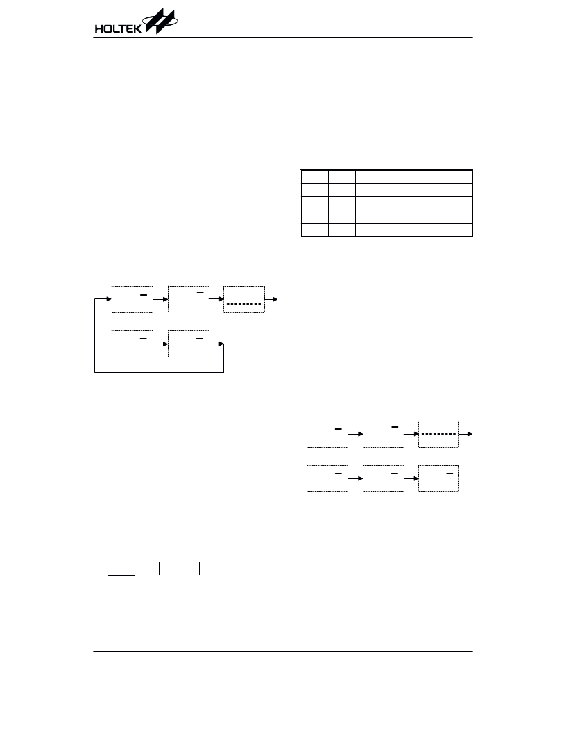
Mode selection sequence and initial value: ( MODE
key)
In digit setting, press the
SET
key
The digit selected will blink at a 1hz rate.
Theblinkingdigit(selecteddigit)willcountupbyitself.
If SET key is pressed 1sec, the digit will count up
rapidly at an 8Hz rate, otherwise count up by 1 every
time it s pressed ( 1sec).
When
Day-Hour-Minute mode, pressing the SET key will re-
set the seconds to 00.
the
colon
( : )
is
blinking
in
the
4
/
5
6 , 7
,
/
8.
7
9
" "
4 & /
/
5
' /
/
5
8.
8.
" "
4
/
5
6 , 7
,
/
" "
4 & /
/
5
' /
/
5
8- +
9
8- +
8- +
4
/
5
8- +
相關(guān)PDF資料 |
PDF描述 |
|---|---|
| HT6751A | Camera Motor Driver (1.5 Channel)(照相機(jī)電機(jī)驅(qū)動器(1.5 通道)) |
| HT6751B | Camera Motor Driver (1.5 Channel)(照相機(jī)電機(jī)驅(qū)動器(1.5 通道)) |
| HT682L | 318 Series of Decoders |
| HT605L | 318 Series of Decoders |
| HT612 | 318 Series of Decoders |
相關(guān)代理商/技術(shù)參數(shù) |
參數(shù)描述 |
|---|---|
| HT6751A | 制造商:HOLTEK 制造商全稱:Holtek Semiconductor Inc 功能描述:Camera Motor Driver (1.5 Channel) |
| HT6751B | 制造商:HOLTEK 制造商全稱:Holtek Semiconductor Inc 功能描述:Camera Motor Driver (1.5 Channel) |
| HT67F30 | 制造商:HOLTEK 制造商全稱:Holtek Semiconductor Inc 功能描述:TinyPowerTM A/D Flash Type 8-Bit MCU with LCD & EEPROM |
| HT67F40 | 制造商:HOLTEK 制造商全稱:Holtek Semiconductor Inc 功能描述:TinyPowerTM A/D Flash Type 8-Bit MCU with LCD & EEPROM |
| HT67F50 | 制造商:HOLTEK 制造商全稱:Holtek Semiconductor Inc 功能描述:TinyPowerTM A/D Flash Type 8-Bit MCU with LCD & EEPROM |
發(fā)布緊急采購,3分鐘左右您將得到回復(fù)。