- 您現(xiàn)在的位置:買賣IC網(wǎng) > PDF目錄385401 > HT6230 (Holtek Semiconductor Inc.) RES THICK FILM 100K OHM 1 W 7KV PDF資料下載
參數(shù)資料
| 型號: | HT6230 |
| 廠商: | Holtek Semiconductor Inc. |
| 英文描述: | RES THICK FILM 100K OHM 1 W 7KV |
| 中文描述: | 紅外遙控編碼器 |
| 文件頁數(shù): | 5/8頁 |
| 文件大?。?/td> | 135K |
| 代理商: | HT6230 |

HT6230
5
April 19, 2000
Functional Description
Key operation
When MS is low, the legal key operation is that
only one ZIN or XIN can be connected to one
DRS driver and if more than one XIN, ZIN or
both are pressed at the same time then the key
operation is recognized as illegal; hence, the os-
cillator will not start. When MS is high, the le-
gal key operation is that exactly one ZIN and
one XIN are connected to two DRS drivers and
other cases of key operation are all considered
as illegal.
However, when one XIN or ZIN is connected to
more than one DRS, the last key scan driver is
to generate output data code.
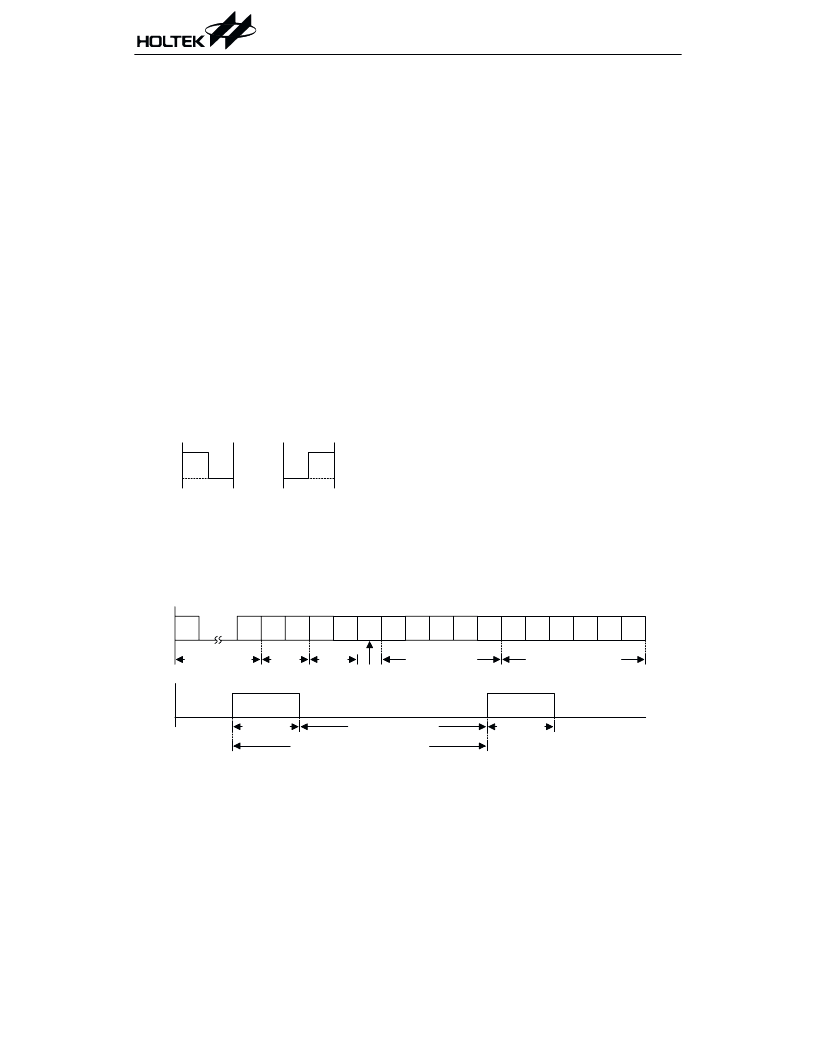
Format of transmission code
The output pin CODE transmits the data code
asacodeformat,asshownatthebottomfigure.
The method of transmitting one code bit is called
biphase transmission and is represented by the
following fig:
Where one code bit time is 3 2
8
T
OSC
. The out-
put signal of the MCODE pin is the signal of the
generated output code modulated by 1/12 of the
system frequency with 1/4 duty cycle. In quies-
cent state both CODE and MCODE are high
impedance.
Key scan drivers
The key scan drivers DRS0 to DRS7 are open
drain NMOS and the outputs of these are all
low in quiescent state. When a legal key opera-
tion is detected, the debounce cycle starts and
at the end of the debounce cycle, the DRS out-
puts are high impedance. Furthermore, the
scanning cycle starts and DRS outputs take
turns to switch to low state.
Programmable output data code
The output data code corresponding to each key
is programmable by hardware mask option.
The PAL circuit is necessary for this purpose.
Operation mode
One-key system mode
The device enters this mode by switching the
MS input pin to low state. The pull-high resis-
tors are connected to all XIN and ZIN inputs
so that all sense inputs are at high state, until
pulled to low state by key operation. In this
mode the legal key operation is that only one
ZIN or XIN can be connected to one DRS.
When a sense input detects a low level, an en-
able signal is generated to latch the system or
command latches. If the sense input belongs
to ZIN, the corresponding system code is gen-
erated and the command code is defined as all
9
& 9
9
& 9
#
#
/ :
+
' 3 / 1 :
1 . :
/ :
: *
3 / :
:
:
0 # # ' :#
/ ' ' :#
Transmission code format
,
,
相關PDF資料 |
PDF描述 |
|---|---|
| HT6240-002 | RES THICK FILM 100 OHM 1 W 7KV |
| HT6264 | CMOS 8K x 8-Bit SRAM |
| HT62L256 | DISPLAY 7-SEG 7.6MM GREEN |
| HT6513 | Mouse Controller |
| HT6523 | PS/2 Mouse Controller |
相關代理商/技術參數(shù) |
參數(shù)描述 |
|---|---|
| HT6240 | 制造商:HOLTEK 制造商全稱:Holtek Semiconductor Inc 功能描述:Infrared Remote Encoder |
| HT6240_02 | 制造商:HOLTEK 制造商全稱:Holtek Semiconductor Inc 功能描述:Infrared Remote Encoder |
| HT6240-001(20DIP) | 制造商:未知廠家 制造商全稱:未知廠家 功能描述:Remote-Control Transmitter/Encoder |
| HT6240-001(20SOIC) | 制造商:未知廠家 制造商全稱:未知廠家 功能描述:Remote-Control Transmitter/Encoder |
| HT6240-001(24SOIC) | 制造商:未知廠家 制造商全稱:未知廠家 功能描述:Remote-Control Transmitter/Encoder |
發(fā)布緊急采購,3分鐘左右您將得到回復。