- 您現(xiàn)在的位置:買賣IC網(wǎng) > PDF目錄385401 > HT6116 (Holtek Semiconductor Inc.) CMOS 2K??8-Bit SRAM PDF資料下載
參數(shù)資料
| 型號: | HT6116 |
| 廠商: | Holtek Semiconductor Inc. |
| 英文描述: | CMOS 2K??8-Bit SRAM |
| 中文描述: | 的CMOS 2K??8位SRAM |
| 文件頁數(shù): | 4/10頁 |
| 文件大小: | 305K |
| 代理商: | HT6116 |

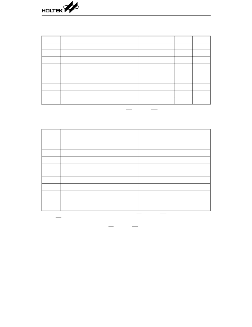
A.C. Characteristics
Read cycle
(V
DD
=5V
±
10%, GND=0V, Ta=–40
°
C to +85
°
C)
Symbol
Parameter
Min.
Typ.
Max.
Unit
t
RC
Read Cycle Time
70
36
—
ns
t
AA
Address Access Time
—
35
70
ns
t
ACS
Chip Select Access Time
—
35
70
ns
t
OE
Output E nable to Output Valid
—
12
40
ns
t
OH
Output Hold from Address Change
10
12
—
ns
t
CLZ
Chip E nable to Output in Low-Z
10
—
—
ns
t
OLZ
Output E nable to Output in Low-Z
10
—
—
ns
t
OHZ
Output Disable to Output in High–Z
0
—
30
ns
t
CHZ
Chip Disable to Output in High-Z
0
—
30
ns
Note: 1. A read occurs during the overlap of a low CS and a high WE
2. t
CHZ
and t
OHZ
are specified by the time when data out is floating
Write cycle
(V
DD
=5V
±
10%, GND=0V, Ta=–40
°
C to +85
°
C)
Symbol
Parameter
Min.
Typ.
Max.
Unit
t
WC
Write Cycle Time
70
36
—
ns
t
DW
Data Set up Time
20
18
—
ns
t
DH
Data Hold Time from Write Time
5
0
—
ns
t
AW
Address Valid to E nd of Write
50
15
—
ns
t
AS
Address Setup Time
20
14
ns
t
WP
Write Pulse Width
25
0
—
ns
t
WR
Write Recovery Time
5
—
—
ns
t
CW
Chip Selection to E nd of Write
35
—
—
ns
t
OW
Output Active from E nd of Write
5
—
—
ns
t
OHZ
Output Disable to Output in High-Z
0
—
40
ns
t
WHZ
Write to Output in High-Z
0
—
50
ns
Note: 1. A write cycle occurs during the overlap of a low CS and a low WE
2. OE may be both high and low in a write cycle
3. t
AS
is specified from CS or WE , whichever occurs last
4. t
WP
is an overlap time of a low CS and a low WE
5. t
WR
, t
DW
and t
DH
is specified from CS or WE , whichever occurs first
6. t
WHZ
is specified by the time when DATA OUT is floating, not defined by output level
7. When I/O pins are data output mode, don’t force inverse signals to those pins
HT6116-70
4
3rd J uly ’97
相關PDF資料 |
PDF描述 |
|---|---|
| HT6116-70 | CMOS 2K??8-Bit SRAM |
| HT6187 | 3(18) Series of Encoders |
| HT6247 | 3(18) Series of Encoders |
| HT6221 | Multi-Purpose Encoders |
| HT6222 | Multi-Purpose Encoders |
相關代理商/技術參數(shù) |
參數(shù)描述 |
|---|---|
| HT6116-70 | 制造商:HOLTEK 制造商全稱:Holtek Semiconductor Inc 功能描述:CMOS 2K??8-Bit SRAM |
| HT6116-70(24DIP) | 制造商:未知廠家 制造商全稱:未知廠家 功能描述:x8 SRAM |
| HT6116-70(24SDIP) | 制造商:未知廠家 制造商全稱:未知廠家 功能描述:x8 SRAM |
| HT6116-70(24SOIC) | 制造商:未知廠家 制造商全稱:未知廠家 功能描述:x8 SRAM |
| HT6116-70-24DIP | 制造商:未知廠家 制造商全稱:未知廠家 功能描述:IC-16K CMOS SRAM |
發(fā)布緊急采購,3分鐘左右您將得到回復。