- 您現(xiàn)在的位置:買賣IC網 > PDF目錄385400 > HT48RB8 (Holtek Semiconductor Inc.) 8-Bit USB Type OTP MCU PDF資料下載
參數(shù)資料
| 型號: | HT48RB8 |
| 廠商: | Holtek Semiconductor Inc. |
| 英文描述: | 8-Bit USB Type OTP MCU |
| 中文描述: | 8位微控制器的USB型檢察官辦公室 |
| 文件頁數(shù): | 15/45頁 |
| 文件大?。?/td> | 281K |
| 代理商: | HT48RB8 |
第1頁第2頁第3頁第4頁第5頁第6頁第7頁第8頁第9頁第10頁第11頁第12頁第13頁第14頁當前第15頁第16頁第17頁第18頁第19頁第20頁第21頁第22頁第23頁第24頁第25頁第26頁第27頁第28頁第29頁第30頁第31頁第32頁第33頁第34頁第35頁第36頁第37頁第38頁第39頁第40頁第41頁第42頁第43頁第44頁第45頁

HT48RB8
Rev. 1.30
15
February 10, 2003
Label (TMR0C)
Bits
Function
0~2
Unused bit, read as 0
TE
3
To define the TMR0 active edge of Timer/Event Counter 0
(0=active on low to high; 1=active on high to low)
TON
4
To enable/disable timer 0 counting
(0=disabled; 1=enabled)
5
Unused bit, read as 0
TM0
TM1
6
7
To define the operating mode
01=Event count mode (external clock)
10=Timer mode (internal clock)
11=Pulse width measurement mode
00=Unused
TMR0C register
Label (TMR1C)
Bits
Function
0~2
Unused bit, read as 0
TE
3
To define the TMR1 active edge of Timer/Event Counter 1
(0=active on low to high; 1=active on high to low)
TON
4
To enable/disable timer 1 counting
(0=disabled; 1=enabled)
5
Unused bit, read as 0
TM0
TM1
6
7
To define the operating mode
01=Event count mode (external clock)
10=Timer mode (internal clock)
11=Pulse width measurement mode
00=Unused
TMR1C register
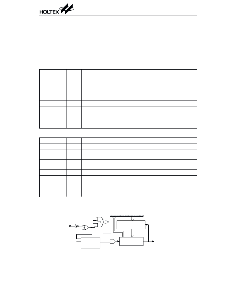
Timer/Event Counter
Two timer/event counters (TMR0, TMR1) are imple-
mented in the microcontroller. The Timer/Event Counter
0 contains an 8-bit programmable count-up counter and
the clock may comes from an external source or from
f
SYS
/4.
The Timer/Event Counter 1 contains an 16-bit program-
mable count-up counter and the clock may come from
an external source or from the system clock divided by
4.
Using the internal clock source, there is only 1 reference
time-base for Timer/Event Counter 0. The internal clock
source is coming from f
SYS
/4.
The external clock input allows the user to count exter-
nal events, measure time intervals or pulse widths.
Using the internal clock source, there is only 1 reference
time-base for Timer/Event Counter 1. The internal clock
source is coming from f
SYS
/4. The external clock input
allows the user to count external events, measure time
intervals or pulse widths.
, !
( +
" $
!
"
(
,
)
3
(
(
,
" (
!
)
3
(
( /
!
,
"
3
% , A
(
%
'
) *
Timer/Event Counter 0
相關PDF資料 |
PDF描述 |
|---|---|
| HT49C10 | 8-BIT MICROCONTROLLER |
| HT49C30L | HDSP-A101 RED DISPLAY, LED, |
| HT49R30 | DISPLAY 7 SEGMENT |
| HT49R30A-1 | DISPL 7 SEG YELLOW |
| HT49C30-1 | 8-Bit LCD Type MCU |
相關代理商/技術參數(shù) |
參數(shù)描述 |
|---|---|
| HT48RU80 | 制造商:HOLTEK 制造商全稱:Holtek Semiconductor Inc 功能描述:I/O Type 8-Bit MCU |
| HT48RXX | 制造商:HOLTEK 制造商全稱:Holtek Semiconductor Inc 功能描述:8-Bit Microcontroller Series |
| HT-49 | 制造商:FCI 功能描述: |
| HT49010576-5 | 制造商:Rennsteig 功能描述:HVT 1.2 TERMINALS 22-18GA |
| HT49010577-5 | 制造商:Rennsteig 功能描述:HVT 1.2 TERMINALS 18-16GA |
發(fā)布緊急采購,3分鐘左右您將得到回復。