- 您現(xiàn)在的位置:買賣IC網(wǎng) > PDF目錄385394 > HSDL-3602-038 (Avago Technologies Ltd.) IrDA㈢ Data 1.4 Compliant 4 Mb/s 3V Infrared Transceiver PDF資料下載
參數(shù)資料
| 型號: | HSDL-3602-038 |
| 廠商: | Avago Technologies Ltd. |
| 英文描述: | IrDA㈢ Data 1.4 Compliant 4 Mb/s 3V Infrared Transceiver |
| 中文描述: | ㈢數(shù)據(jù)的IrDA 1.4兼容4 Mb / s的3V的紅外收發(fā)器 |
| 文件頁數(shù): | 13/27頁 |
| 文件大小: | 388K |
| 代理商: | HSDL-3602-038 |
第1頁第2頁第3頁第4頁第5頁第6頁第7頁第8頁第9頁第10頁第11頁第12頁當(dāng)前第13頁第14頁第15頁第16頁第17頁第18頁第19頁第20頁第21頁第22頁第23頁第24頁第25頁第26頁第27頁
13
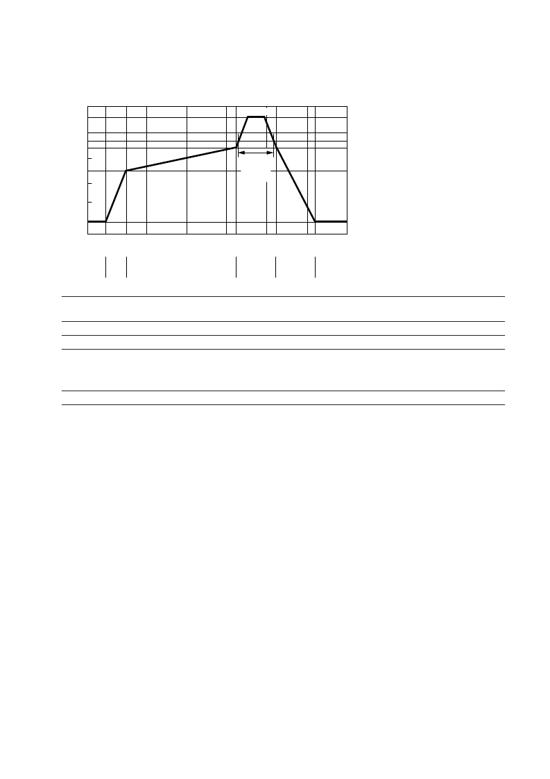
The reflow profile is a straight-line representation of
a nominal temperature profile for a convective reflow
solder process. The temperature profile is divided into
four process zones, each with different T/time tem-
perature change rates. The T/time rates are detailed
in the following table. The temperatures are measured
at the component to printed circuit board connections.
In process zone P1, the PC board and HSDL-3602 cas-
tellation pins are heated to a temperature of 160°C to
activate the flux in the solder paste. The temperature
ramp up rate, R1, is limited to 4°C per second to allow
for even heating of both the PC board and HSDL-3602
castellations.
Process zone P2 should be of sufficient time duration
(60 to 120 seconds) to dry the solder paste. The tem-
perature is raised to a level just below the liquidus point
of the solder, usually 200°C (392°F).
Process zone P3 is the solder reflow zone. In zone P3, the
temperature is quickly raised above the liquidus point
of solder to 255°C (491°F) for optimum results. The
dwell time above the liquidus point of solder should
Process Zone
Heat Up
Solder Paste Dry
Solder Reflow
Cool Down
Symbol
P1, R1
P2, R2
P3, R3
P3, R4
P4, R5
T
25C to 160C
160C to 200C
200C to 255C
(260C at 10 seconds max.)
255C to 200C
200C to 25C
Maximum
T/time
4C/s
0.5C/s
4C/s
–6C/s
–6C/s
Recommended Reflow Profile
be between 20 and 60 seconds. It usually takes about
20 seconds to assure proper coalescing of the solder
balls into liquid solder and the formation of good solder
connections. Beyond a dwell time of 60 seconds, the
intermetallic growth within the solder connections be-
comes excessive, resulting in the formation of weak and
unreliable connections. The temperature is then rapidly
reduced to a point below the solidus temperature of
the solder, usually 200°C (392°F), to allow the solder
within the connections to freeze solid.
Process zone P4 is the cool down after solder freeze. The
cool down rate, R5, from the liquidus point of the solder
to 25°C (77°F) should not exceed 6°C per second maxi-
mum. This limitation is necessary to allow the PC board
and HSDL-3602 castellations to change dimensions
evenly, putting minimal stresses on the HSDL-3602
transceiver.
0
t-TIME (SECONDS)
T
230
220
200
180
160
120
80
50
150
100
200
250
300
255
P1
HEAT
UP
P2
SOLDER PASTE DRY
P3
SOLDER
REFLOW
P4
COOL
DOWN
25
R1
R2
R3
R4
R5
60 sec.
MAX.
ABOVE
220 C
MAX. 260 C
相關(guān)PDF資料 |
PDF描述 |
|---|---|
| HSDL-3603 | IrDA㈢ Data Compliant 4 Mbit/s Infrared Transceiver |
| HSDL-3603-207 | IrDA㈢ Data Compliant 4 Mbit/s Infrared Transceiver |
| HSDL-3603-208 | IrDA㈢ Data Compliant 4 Mbit/s Infrared Transceiver |
| HSDL-4250 | High-Performance T-1 (5mm) AlGaAs Infrared (870nm) Lamp |
| HSDL-4251 | High-Performance T-1 (5mm) AlGaAs Infrared (870nm) Lamp |
相關(guān)代理商/技術(shù)參數(shù) |
參數(shù)描述 |
|---|---|
| HSDL-3603 | 制造商:AVAGO 制造商全稱:AVAGO TECHNOLOGIES LIMITED 功能描述:IrDA㈢ Data Compliant 4 Mbit/s Infrared Transceiver |
| HSDL-3603-007 | 制造商:Lite-On Semiconductor Corporation 功能描述:IRDA TX/RX 4MBPS 2.7V TO 5.25V - Bulk 制造商:Avago Technologies 功能描述:TRANSCEIVER SMD IRDA1.4 4MB |
| HSDL-3603-007 | 制造商:Avago Technologies 功能描述:TRANSCEIVER SMD IRDA1.4 4MB |
| HSDL-3603-017 | 制造商:Lite-On Semiconductor Corporation 功能描述:IRDA TX/RX 4MBPS 3.3V/5V - Bulk |
| HSDL-3603-207 | 制造商:AVAGO 制造商全稱:AVAGO TECHNOLOGIES LIMITED 功能描述:IrDA㈢ Data Compliant 4 Mbit/s Infrared Transceiver |
發(fā)布緊急采購,3分鐘左右您將得到回復(fù)。