- 您現(xiàn)在的位置:買賣IC網(wǎng) > PDF目錄385388 > HMP8191CN (INTERSIL CORP) NTSC/PAL Video Encoder PDF資料下載
參數(shù)資料
| 型號(hào): | HMP8191CN |
| 廠商: | INTERSIL CORP |
| 元件分類: | 顏色信號(hào)轉(zhuǎn)換 |
| 英文描述: | NTSC/PAL Video Encoder |
| 中文描述: | COLOR SIGNAL ENCODER, PQFP64 |
| 封裝: | 14 X 14 MM, PLASTIC, MO-108BD-2, QFP-64 |
| 文件頁(yè)數(shù): | 20/32頁(yè) |
| 文件大?。?/td> | 227K |
| 代理商: | HMP8191CN |
第1頁(yè)第2頁(yè)第3頁(yè)第4頁(yè)第5頁(yè)第6頁(yè)第7頁(yè)第8頁(yè)第9頁(yè)第10頁(yè)第11頁(yè)第12頁(yè)第13頁(yè)第14頁(yè)第15頁(yè)第16頁(yè)第17頁(yè)第18頁(yè)第19頁(yè)當(dāng)前第20頁(yè)第21頁(yè)第22頁(yè)第23頁(yè)第24頁(yè)第25頁(yè)第26頁(yè)第27頁(yè)第28頁(yè)第29頁(yè)第30頁(yè)第31頁(yè)第32頁(yè)

20
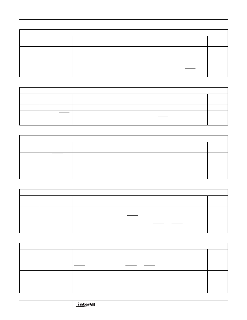
TABLE 35. START V_BLANK LOW REGISTER
SUB ADDRESS = 23
H
BIT
NUMBER
FUNCTION
DESCRIPTION
RESET
STATE
7-0
LSB Assert BLANK
Output Signal
(Vertical)
This 8-bit register is cascaded with Start V_Blank High Register to form a 9-bit
start_vertical_blank register. During normal operation, it specifies the line number (n) to start
ignoring pixel input data (and what line number to start blanking the output video) each odd
field; for even fields, it occurs on line (n + 262) or (n + 313).
The leading edge of VSYNC at the start of an odd field is count 000
H
(note that this does not
follow standard NTSC or PAL line numbering). This register is ignored unless BLANK is con-
figured as an output.
03
H
TABLE 36. START V_BLANK HIGH REGISTER
SUB ADDRESS = 24
H
BIT
NUMBER
FUNCTION
DESCRIPTION
RESET
STATE
7-1
Reserved
0000000
B
0
MSB Assert BLANK
Output Signal
(Vertical)
This 1-bit register is cascaded with Start V_Blank Low Register to form a 9-bit
start_vertical_blank register. This register is ignored unless BLANK is configured as an output.
1
B
TABLE 37. END V_BLANK REGISTER
SUB ADDRESS = 25
H
BIT
NUMBER
FUNCTION
DESCRIPTION
RESET
STATE
7-0
Negate BLANK
Output Signal
(Vertical)
During normal operation, this 8-bit register specifies the line number (n) to start inputting pixel
input data (and what line number to start generating active output video) each odd field; for
even fields, it occurs on line (n + 262) or (n + 313).
The leading edge of VSYNC at the start of an odd field is count 000
H
(note that this does not
follow standard NTSC or PAL line numbering). This register is ignored unless BLANK is con-
figured as an output.
13
H
TABLE 38. FIELD CONTROL REGISTER 1
SUB ADDRESS = 26
H
BIT
NUMBER
FUNCTION
DESCRIPTION
RESET
STATE
7-0
Field Detect
Window Size Low
This 8-bit register is cascaded with Field Detect Window Size High to form a 9-bit Field Detect
Window Size value. The value specifies the number of 1x clock cycles in the detection window
before and after the selected edge of VSYNC. It may range from 0 to 511. If the leading edge
of HSYNC occurs within the window, it is the start of an odd or even field, as specified by the
FIELD Detect Select bit. This register is ignored unless HSYNC and VSYNC are configured
as inputs.
80
H
TABLE 39. FIELD CONTROL REGISTER 2
SUB ADDRESS = 27
H
BIT
NUMBER
FUNCTION
DESCRIPTION
RESET
STATE
7-4
Half Line Count
Reset Value
These bits specify the value to load to the vertical half line counter when the selected edge of
VSYNC. The value is ignored when HSYNC and VSYNC are configured as outputs.
00000
B
2
VSYNC Edge
Select
This bit specifies whetherthe encoder uses the leading or trailing edge ofVSYNC to determine
the field and to reset the half line counter. It is ignored unless HSYNC and VSYNC are config-
ured as inputs.
0 = leading edge
1 = trailing edge
0
B
HMP8190, HMP8191
相關(guān)PDF資料 |
PDF描述 |
|---|---|
| HMPS650 | NPN SILICON TRANSISTOR |
| HMPSH10 | NPN EPITAXIAL PLANAR TRANSISTOR |
| HMS77C1000A | 8-BIT SINGLE-CHIP MICROCONTROLLERS |
| HMS77C1001A | 8-BIT SINGLE-CHIP MICROCONTROLLERS |
| HMS81020TL | HYNIX SEMICONDUCTOR 8-BIT SINGLE-CHIP MICROCONTROLLERS |
相關(guān)代理商/技術(shù)參數(shù) |
參數(shù)描述 |
|---|---|
| HMP8201CN | 制造商:未知廠家 制造商全稱:未知廠家 功能描述:Compression/Expansion Circuit |
| HMP820SGR32GM | 制造商:Advanced Micro Devices 功能描述:PHENOM II MOBILE X3 P820 25W S1G4 - Trays |
| HMP9701 | 制造商:INTERSIL 制造商全稱:Intersil Corporation 功能描述:AC’97 Audio Codec |
| HMP9701A | 制造商:INTERSIL 制造商全稱:Intersil Corporation 功能描述:AC’97 Audio Codec |
| HMP9701ACN | 制造商:Rochester Electronics LLC 功能描述:- Bulk |
發(fā)布緊急采購(gòu),3分鐘左右您將得到回復(fù)。