- 您現(xiàn)在的位置:買賣IC網(wǎng) > PDF目錄385376 > HFA5250CB (INTERSIL CORP) 500MHz, Ultra High Speed Monolithic Pin Driver PDF資料下載
參數(shù)資料
| 型號: | HFA5250CB |
| 廠商: | INTERSIL CORP |
| 元件分類: | 外設(shè)及接口 |
| 英文描述: | 500MHz, Ultra High Speed Monolithic Pin Driver |
| 中文描述: | BUF OR INV BASED PRPHL DRVR, PDSO28 |
| 封裝: | SOIC-28 |
| 文件頁數(shù): | 2/5頁 |
| 文件大小: | 577K |
| 代理商: | HFA5250CB |

8-108
Absolute Maximum Ratings
Thermal Information
Supply Voltage . . . . . . . . . . . . . . . . . . . . . . . . . . . . . . . . . . . . . . 17V
Differential Input Voltage . . . . . . . . . . . . . . . . . . . . . . . . . . . . . . . 5V
Continuous Output Current. . . . . . . . . . . . . . . . . . . .160mA (Note 1)
Operating Conditions
Temperature Range . . . . . . . . . . . . . . . . . . . . . . . . . . . 0
o
C to 70
o
C
Thermal Resistance (Typical, Note 2)
SOIC Package. . . . . . . . . . . . . . . . . . .
Maximum Package Power Dissipation
SOIC Package with Still Air at 50
o
C . . . . . . . . . . . . . . . . . . 1.43W
SOIC Package with 400lfpm Air at 70
o
C. . . . . . . . . . . . . . . 1.45W
Maximum Junction Temperature (Plastic Package) . . . . . . . . 150
o
C
Maximum Storage Temperature Range . . . . . . . . . -65
o
C to 150
o
C
Maximum Lead Temperature (Soldering 10s). . . . . . . . . . . . 300
o
C
(SOIC - Lead Tips Only)
θ
JA
(
o
C/W)
70
θ
JC
(
o
C/W)
55
CAUTION: Stresses above those listed in “Absolute Maximum Ratings” may cause permanent damage to the device. This is a stress only rating and operation
of the device at these or any other conditions above those indicated in the operational sections of this specification is not implied.
NOTES:
1. Internal Power Dissipation may limit Output Current below 160mA.
2.
θ
JA
is measured with the component mounted on an evaluation PC board in free air.
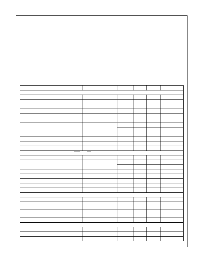
Electrical Specifications
V
CC
= +10V, V
EE
= -5.2V, Unless Otherwise Specified
PARAMETER
TEST CONDITIONS
TEMP. (
o
C)
MIN
TYP
MAX
UNITS
INPUT CHARACTERISTICS
(V
HIGH
, V
LOW
)
V
HIGH
Input Offset Voltage
V
LOW
Input Offset Voltage
V
HIGH
Input Bias Current
V
LOW
Input Bias Current
V
HIGH
Voltage Range
V
HIGH
= 0
V
LOW
= 0
V
HIGH
= 5V
V
LOW
= 0V
Note 6
25
-200
-100
30
mV
25
-200
-100
30
mV
25
-150
50
250
μ
A
μ
A
25
-350
-100
150
25
-2.6
-
7.5
V
25
V
EE
+2.6
-2.7
-
V
CC
-2.5
7.4
V
V
LOW
Voltage Range
Note 6
25
-
V
25
V
EE
+2.5
0.2
-
V
CC
-2.6
10.2
V
V
HIGH
to V
LOW
Differential Voltage Range
Input Resistance
25
-
V
V
IN
= -2V to 7V
25
-
10
-
k
Input Capacitance
25
-
5
-
pF
Input Noise Voltage
10Hz to 1MHz
25
-
20
-
μ
V
P-P
LOGIC INPUT CHARACTERISTICS
(Data, Data, HiZ, HiZ)
Input Offset Voltage
25
-
±
250
-
mV
Input Voltage Range
Note 6
25
-2.0
-
7.0
V
25
V
EE
+3.2
-25
-
V
CC
-3.0
200
V
Input High Current
V
IH
= 0V, V
IL
= -2V
V
IH
= 0V, V
IL
= -2V
V
CM
= -2V to 7V
V
DIFF
= 0V to 5V
25
50
μ
A
μ
A
M
k
Input Low Current
25
-400
-150
25
Common Mode Input Resistance
25
-
1
-
Differential Input Resistance
25
-
100
-
Input Capacitance
25
-
3
-
pF
TRANSFER CHARACTERISTICS
V
HIGH
/V
LOW
Voltage Gain
V
HIGH
/V
LOW
Linearity Error
V
HIGH
, V
LOW
= 0V to 5V
V
HIGH
, V
LOW
= 0V to 5V,
FS = 5V
25
0.95
0.97
1.0
V/V
25
-0.5
±
0.2
0.5
%
V
HIGH
/V
LOW
Linearity Error
V
HIGH
, V
LOW
= -2V to 7V,
FS = 9V
25
-1.2
±
0.6
1.2
%
V
HIGH
/V
LOW
-3dB Bandwidth
SWITCHING CHARACTERISTICS
(Z
LOAD
= 10 Inches of RG-58, V
HIGH
= 3V, V
LOW
= 0V, V
DATA
= -1.8V to -1.0V, Measured 50% to 50% pts)
Propagation Delay
Note 3
200mV
P-P
25
-
500
-
MHz
25
-
2
-
ns
Propagation Delay Jitter, 1 Sigma
25
-
30
-
ps
Propagation Delay Match (Rising vs Falling Edge)
Note 3
25
-
150
-
ps
HFA5250
相關(guān)PDF資料 |
PDF描述 |
|---|---|
| HFA70NC60CSL | Ultrafast, Soft Recovery Diode |
| HFA75MB40C | Ultrafast, Soft Recovery Diode HEXFRED |
| HFA80NC40C | Ultrafast, Soft Recovery Diode |
| HFB06PB120 | HEXFRED Ultrafast, Soft Recovery Diode |
| HFB06TB120 | Ultrafast, Soft Recovery Diode |
相關(guān)代理商/技術(shù)參數(shù) |
參數(shù)描述 |
|---|---|
| HFA5251 | 制造商:INTERSIL 制造商全稱:Intersil Corporation 功能描述:800MHz Monolithic Pin Driver |
| HFA5251 WAF | 制造商:Intersil Corporation 功能描述: |
| HFA5251Y | 制造商:未知廠家 制造商全稱:未知廠家 功能描述:Pin ATE Driver |
| HFA5253 | 制造商:HARRIS 制造商全稱:HARRIS 功能描述:800MHz, Ultra High-Speed Monolithic Pin Driver |
| HFA5253CB | 制造商:HARRIS 制造商全稱:HARRIS 功能描述:800MHz, Ultra High-Speed Monolithic Pin Driver |
發(fā)布緊急采購,3分鐘左右您將得到回復(fù)。