- 您現(xiàn)在的位置:買賣IC網(wǎng) > PDF目錄384399 > HE84G770B (King Billion Electronics Co., Ltd.) 8-BIT MICRO-CONTROLLER PDF資料下載
參數(shù)資料
| 型號: | HE84G770B |
| 廠商: | King Billion Electronics Co., Ltd. |
| 英文描述: | 8-BIT MICRO-CONTROLLER |
| 中文描述: | 8位微控制器 |
| 文件頁數(shù): | 15/61頁 |
| 文件大小: | 817K |
| 代理商: | HE84G770B |
第1頁第2頁第3頁第4頁第5頁第6頁第7頁第8頁第9頁第10頁第11頁第12頁第13頁第14頁當(dāng)前第15頁第16頁第17頁第18頁第19頁第20頁第21頁第22頁第23頁第24頁第25頁第26頁第27頁第28頁第29頁第30頁第31頁第32頁第33頁第34頁第35頁第36頁第37頁第38頁第39頁第40頁第41頁第42頁第43頁第44頁第45頁第46頁第47頁第48頁第49頁第50頁第51頁第52頁第53頁第54頁第55頁第56頁第57頁第58頁第59頁第60頁第61頁
2.
3.
King Billion Electronics Co., Ltd
駿
億
電
子
股
份
有
限
公
司
HE84G770
HE80004H SERIES
October 31, 2003
This specification is subject to change without notice. Please contact sales person for the latest version before use.
15
Version:V1.1
Make a dummy read to EXMD register to reset the AC pointer.
Set up the address for transferring data by first writing to ACL, and then ACH and ACP with the first
3 writes to register.
Start writing to addressed device by first writing 1 byte of data to EXMD register, clear WR bit of
CMD register and set it again, the AC will increment with each write pulse.
To read addressed device, clear RD bit of EXMC register, read EXMD register and set RD bit again.
The AC will also increment with each read pulse. Read back for verification is optional. Please note
that read back can also be made through external address and data bus when the bus is switched back
to program bus.
Switch back to normal bus for program execution and data access by clearing the DNLD bit of
EXMC register.
4.
5.
6.
Please note that NOR FLASH memory from different manufacturers such as Intel, AMD, SST, etc.
requires various command sequence to set up. Programmer still needs to follow the respective
specifications of the vendors.
8.
LCD Display RAM Map
The gray-scale LCD driver can be configured to be a 16 gray-scale, 4 gray-scales or black and white
display by mask option MO_GRAY_MODE.
MO_GRAY_MODE[1..0]
00
01
10
11
Gray levels
16
4
2 (B/W)
2 (B/W)
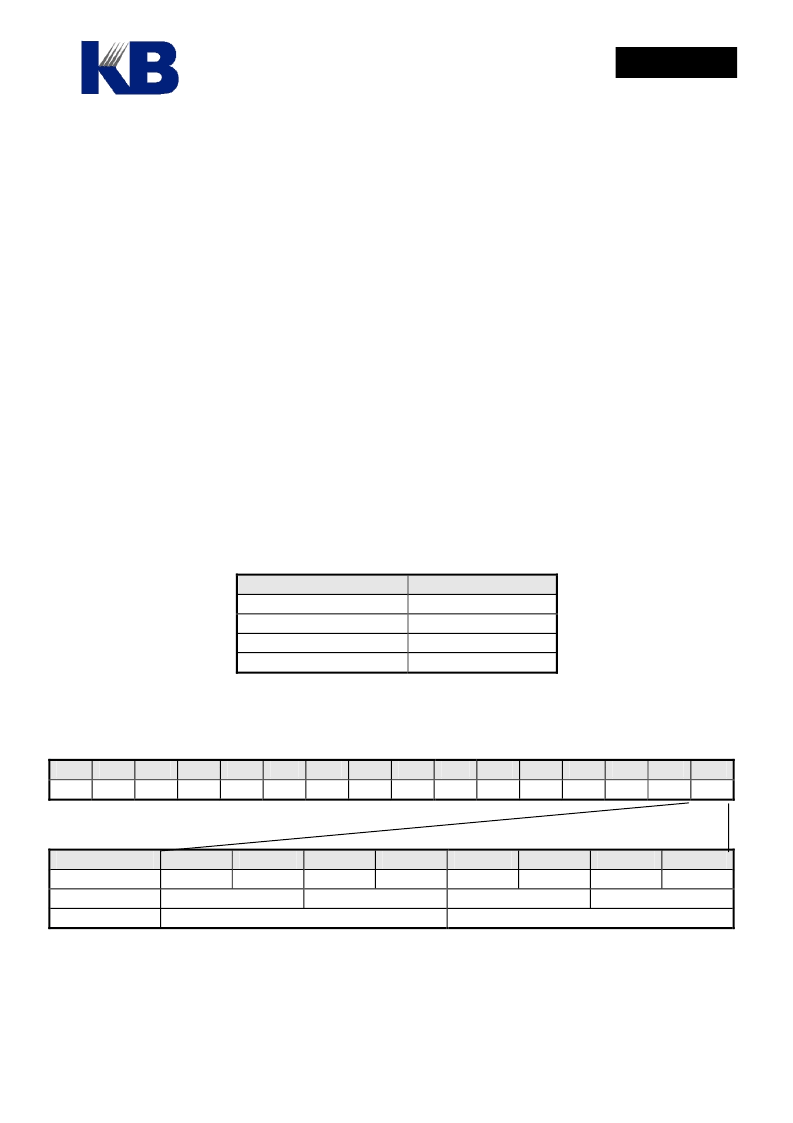
For 4 gray-scale displays, 2-bit of RAM is required for each pixel and 4 bit for 16 gray-scale display, 1-bit
for black and white display. For different LCD configuration, the LCD display RAM is arranged
differently. The following figure shows one byte of RAM in different LCD configurations:
0F
xx
0E
xx
0D
xx
0C
xx
0B
xx
0A
xx
09
xx
08
xx
07
xx
06
xx
05
xx
04
xx
03
xx
02
xx
01
xx
00
xx
Black/White
4 Gray scales
16 Gray scales
Bit 7
SEG7
Bit 6
SEG6
Bit 5
SEG5
Bit 4
SEG4
Bit 3
SEG3
Bit 2
SEG2
Bit 1
SEG1
Bit 0
SEG0
SEG3
SEG2
SEG1
SEG0
SEG1
SEG0
The 16 Gray Scale register GRAY0 ~ GRAYF is the mapping register between the levels selected in
RAM and the real gray scale. In other words, if the content of GRAY0 is 0x03, when value of a certain
pixel is 0, the displayed effect will correspond to actual gray level 3. The 16 gray scale display use all 16
registers GRAY0 ~ GRAYF to select among 32 available gray levels to correspond to level 0 ~ 15, while
相關(guān)PDF資料 |
PDF描述 |
|---|---|
| HE85750 | 8-bit Micro-controller |
| HE89410 | 8-BIT MICRO-CONTROLLER |
| HE89810 | 8-BIT MICRO-CONTROLLER |
| HE89820 | 8-BIT MICRO-CONTROLLER |
| HE89A20 | 8-BIT MICRO-CONTROLLER |
相關(guān)代理商/技術(shù)參數(shù) |
參數(shù)描述 |
|---|---|
| HE850 | 制造商:HVPSI 制造商全稱:High Voltage Power Solutions, Inc. 功能描述:SECONDARY SURGE "LIGHTNING" ARRESTER |
| HE8550 | 制造商:HSMC 制造商全稱:HSMC 功能描述:PNP EPITAXIAL PLANAR TRANSISTOR |
| HE8550_05 | 制造商:UTC-IC 制造商全稱:UTC-IC 功能描述:LOW VOLTAGE HIGH CURRENT SMALL SIGNAL PNP TRANSISTOR |
| HE8550_10 | 制造商:UTC-IC 制造商全稱:UTC-IC 功能描述:LOW VOLTAGE HIGH CURRENT SMALL SIGNAL PNP TRANSISTOR |
| HE8550-C-AB3-B | 制造商:UTC-IC 制造商全稱:UTC-IC 功能描述:LOW VOLTAGE HIGH CURRENT SMALL SIGNAL PNP TRANSISTOR |
發(fā)布緊急采購,3分鐘左右您將得到回復(fù)。