- 您現(xiàn)在的位置:買賣IC網(wǎng) > PDF目錄370431 > HBFP-0420-TR3 TRANSISTOR | BJT | NPN | 4.5V V(BR)CEO | 36MA I(C) | SOT-343R PDF資料下載
參數(shù)資料
| 型號: | HBFP-0420-TR3 |
| 英文描述: | TRANSISTOR | BJT | NPN | 4.5V V(BR)CEO | 36MA I(C) | SOT-343R |
| 中文描述: | 晶體管|晶體管|叩| 4.5VV(巴西)總裁| 36MA一(c)|的SOT - 343R |
| 文件頁數(shù): | 3/10頁 |
| 文件大小: | 85K |
| 代理商: | HBFP-0420-TR3 |
3
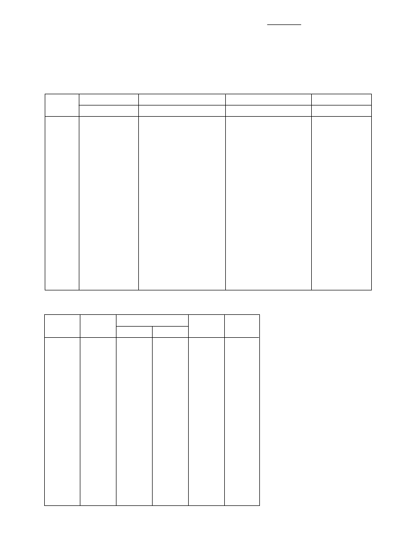
HBFP-0405 Typical Scattering Parameters,
V
CE
= 2 V, I
C
= 2 mA, T
C
= 25
°
C
S
11
GHz
Mag
Ang
0.1
0.910
-4.2
0.5
0.889
-21.2
0.9
0.855
-37.6
1.0
0.841
-41.4
1.5
0.774
-60.9
1.8
0.730
-72.0
2.0
0.701
-79.4
2.5
0.634
-96.0
3.0
0.570
-112.3
3.5
0.521
-127.0
4.0
0.477
-141.2
4.5
0.443
-154.7
5.0
0.412
-168.7
5.5
0.386
177.1
6.0
0.372
162.2
6.5
0.369
147.7
7.0
0.366
130.7
7.5
0.370
116.2
8.0
0.387
102.9
8.5
0.405
91.4
9.0
0.421
80.9
9.5
0.437
70.5
10.0
0.454
60.3
Freq.
S
21
Mag
6.665
6.496
6.101
5.993
5.484
5.164
4.964
4.450
3.996
3.620
3.320
3.047
2.829
2.646
2.493
2.371
2.258
2.141
2.042
1.937
1.834
1.753
1.669
S
12
Mag
0.003
0.017
0.030
0.033
0.048
0.055
0.059
0.068
0.073
0.077
0.080
0.082
0.084
0.087
0.089
0.093
0.096
0.100
0.103
0.105
0.109
0.112
0.115
S
22
dB
16.5
16.3
15.7
15.6
14.8
14.3
13.9
13.0
12.0
11.2
10.4
9.7
9.0
8.5
7.9
7.5
7.1
6.6
6.2
5.7
5.3
4.9
4.4
Ang
176.2
160.6
146.0
142.5
125.9
116.8
110.9
97.0
84.7
73.4
62.9
53.6
44.2
34.9
25.6
16.8
8.1
-1.3
-9.8
-18.3
-26.6
-35.2
-43.7
dB
-49.6
-35.6
-30.4
-29.5
-26.4
-25.1
-24.5
-23.4
-22.7
-22.3
-21.9
-21.8
-21.5
-21.3
-21.0
-20.7
-20.4
-20.0
-19.8
-19.5
-19.3
-19.0
-18.8
Ang
88.5
80.5
71.9
69.6
57.5
50.6
46.4
37.0
28.7
21.7
15.6
10.7
6.0
1.6
-2.1
-7.0
-10.7
-14.7
-19.2
-23.6
-27.9
-32.4
-37.0
Mag
0.995
0.982
0.951
0.937
0.880
0.843
0.817
0.758
0.708
0.669
0.634
0.613
0.591
0.571
0.550
0.525
0.496
0.471
0.444
0.425
0.411
0.398
0.385
Ang
-2.2
-10.5
-18.8
-20.9
-30.8
-36.4
-39.8
-47.8
-54.9
-60.9
-66.4
-71.5
-76.4
-80.8
-86.1
-90.5
-95.2
-100.2
-106.7
-113.9
-121.3
-127.7
-133.5
HBFP-0405 Noise Parameters:
V
CE
= 2 V, I
C
= 2 mA
Freq.
GHz
F
min
dB
Γ
opt
R
N
/50
20.9
20.6
19.2
18.5
18.0
16.6
15.6
14.2
13.0
12.1
10.9
10.5
10.4
10.2
11.0
12.0
13.7
15.9
18.6
22.3
26.3
G
a
dB
Mag
Ang
0.9
1.0
1.5
1.8
2.0
2.5
3.0
3.5
4.0
4.5
5.0
5.5
6.0
6.5
7.0
7.5
8.0
8.5
9.0
9.5
10.0
1.07
1.09
1.19
1.25
1.29
1.39
1.48
1.57
1.70
1.78
1.87
2.00
2.10
2.18
2.29
2.35
2.50
2.65
2.76
2.93
2.94
0.569
0.558
0.504
0.474
0.456
0.423
0.391
0.352
0.318
0.290
0.257
0.215
0.179
0.157
0.125
0.116
0.140
0.163
0.191
0.226
0.254
9.3
11.6
22.0
28.7
33.6
48.2
59.3
72.1
83.1
93.9
107.3
118.3
133.7
153.1
-179.2
-154.8
-123.4
-104.1
-89.2
-73.4
-61.4
23.46
22.67
19.64
18.28
17.50
15.91
14.39
13.29
12.29
11.43
10.71
10.03
9.47
8.97
8.50
7.98
7.63
7.21
6.81
6.51
6.16
S and noise parameters are measured
on a microstrip line made on
0.025 inch thick alumina carrier. The
input reference plane is at the end of
the base lead, the output reference
plane is at the end of the collector
lead. S and noise parameters include
the effect of four plated through via
holes connecting emitter landing pads
on the top of test carrier to the
microstrip ground plane on the
bottom side of the carrier. Two
0.020 inch diameter via holes are
placed within 0.010 inch from each
emitter lead contact point, one via on
each side of that point.
相關(guān)PDF資料 |
PDF描述 |
|---|---|
| HBFP-0450 | 3V High Performance Transistor |
| HBFP-0450-TR3 | TRANSISTOR | BJT | NPN | 4.5V V(BR)CEO | 100MA I(C) | SOT-343 |
| HBFP-0405-TR1 | High Performance Isolated Collector Silicon Bipolar Transistor |
| HBFP-0405-TR2 | High Performance Isolated Collector Silicon Bipolar Transistor |
| HBFP0405 | High Performance Isolated Collector Silicon Bipolar Transistor |
相關(guān)代理商/技術(shù)參數(shù) |
參數(shù)描述 |
|---|---|
| HBFP-0450 | 制造商:未知廠家 制造商全稱:未知廠家 功能描述:3V High Performance Transistor |
| HBFP-0450-TR1 | 制造商:HEWLETT 功能描述: |
| HBFP-0450-TR3 | 制造商:未知廠家 制造商全稱:未知廠家 功能描述:TRANSISTOR | BJT | NPN | 4.5V V(BR)CEO | 100MA I(C) | SOT-343 |
| HBFR113-S | 制造商:SEOUL 制造商全稱:Seoul Semiconductor 功能描述:Surface-mounted chip LED device |
| HBFR-1602 | 制造商:未知廠家 制造商全稱:未知廠家 功能描述:Telecomm/Datacomm |
發(fā)布緊急采購,3分鐘左右您將得到回復(fù)。