- 您現(xiàn)在的位置:買賣IC網(wǎng) > PDF目錄370423 > HAL114SF-E (MICRONAS SEMICONDUCTOR HOLDING AG) Hall Effect Sensor Family PDF資料下載
參數(shù)資料
| 型號(hào): | HAL114SF-E |
| 廠商: | MICRONAS SEMICONDUCTOR HOLDING AG |
| 元件分類: | 磁阻傳感器 |
| 英文描述: | Hall Effect Sensor Family |
| 中文描述: | MAGNETIC FIELD SENSOR-HALL EFFECT, -17-11mT, 0.13-0.28V, RECTANGULAR, SURFACE MOUNT |
| 封裝: | PLASTIC, SOT-89B, 4 PIN |
| 文件頁(yè)數(shù): | 14/17頁(yè) |
| 文件大小: | 131K |
| 代理商: | HAL114SF-E |
第1頁(yè)第2頁(yè)第3頁(yè)第4頁(yè)第5頁(yè)第6頁(yè)第7頁(yè)第8頁(yè)第9頁(yè)第10頁(yè)第11頁(yè)第12頁(yè)第13頁(yè)當(dāng)前第14頁(yè)第15頁(yè)第16頁(yè)第17頁(yè)
HAL11x
14
Micronas
5. Application Notes
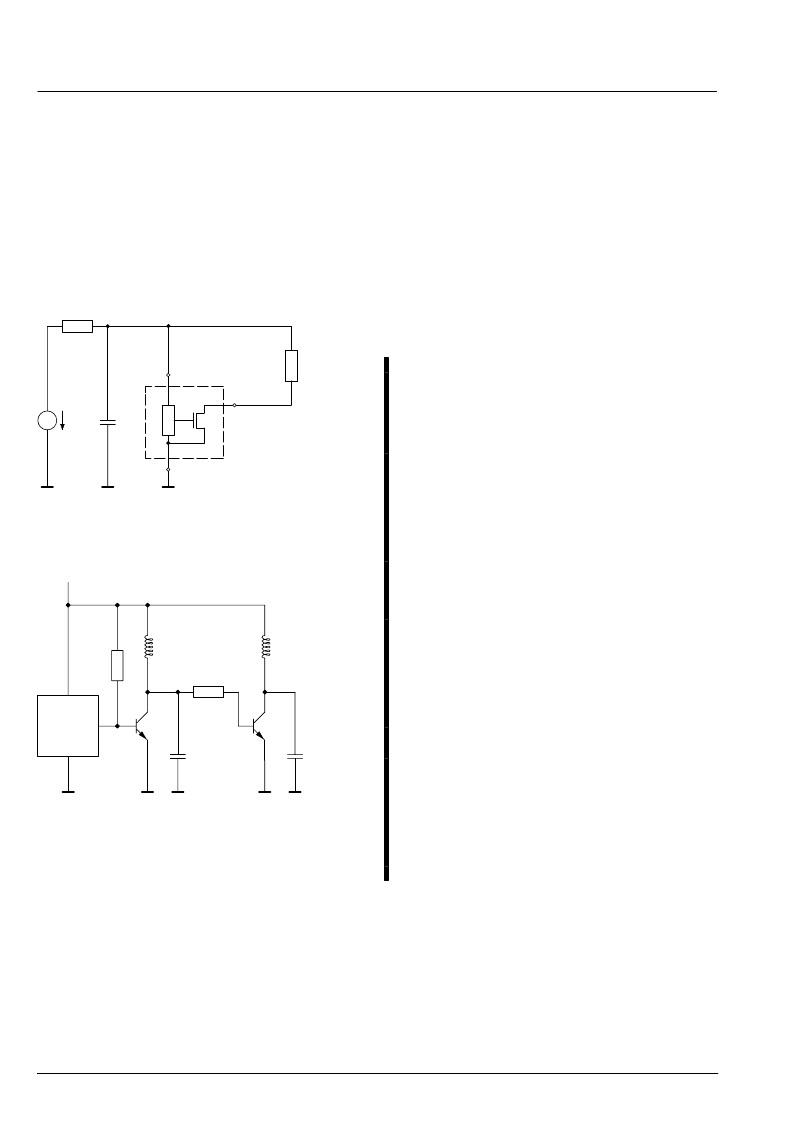
5.1. Application Circuit
The HAL11x sensors can operate without external com-
ponents. For applications with disturbances on the sup-
ply line or radiated disturbances, a series resistor and a
capacitor are recommended (see Fig. 5–1).
The series resistor and the capacitor should be placed
as closely as possible to the sensor.
OUT
GND
3
2
1
V
DD
4.7 nF
V
DD
R
V
220
R
L
Fig. 5–1:
Recommended application circuit
HAL115
1
2
3
3.3 k
R
1
L
1
R
2
3.3 k
L
2
C
1
C
2
2.2
μ
/50 V
2.2
μ
/50 V
V
DD
Fig. 5–2:
Recommended application circuit
for DC fans
5.2. Ambient Temperature
Due to the internal power dissipation, the temperature
on the silicon chip (junction temperature T
J
) is higher
than the temperature outside the package (ambient tem-
perature T
A
).
T
J
= T
A
+
T
At static conditions, the following equation is valid:
T = I
DD
* V
DD
* R
th
For typical values, use the typical parameters. For worst
case calculation, use the max. parameters for I
DD
and
R
th
, and the max. value for V
DD
from the application.
For all sensors, the junction temperature range T
J
is
specified. The maximum ambient temperature T
Amax
can be calculated as:
T
Amax
= T
Jmax
–
T
5.3. Extended Operating Conditions
All sensors fulfill the electrical and magnetic characteris-
tics when operated within the Recommended Operating
Conditions (see page 6).
Please use the sensors of the HAL 5xx family if lower op-
eration voltage, lower current consumption or tighter
magnetic specifications required.
5.4. Start-up Behavior
The sensors have an initialization time (enable time
t
en(O)
) after applying the supply voltage. This parameter
t
en(O)
is specified in the Electrical Characteristics (see
page 7).
During the initialization time, the output state is not de-
fined and can toggle. After t
en(O)
, the output will be low
if the applied magnetic field B is above B
ON
or high if B
is below B
OFF
.
For magnetic fields between B
OFF
and B
ON
, the output
state of the HAL sensor after applying V
DD
will be either
low or high. In order to achieve a well-defined output
state, the applied magnetic field must be above B
ONmax
,
respectively, below B
OFFmin
.
相關(guān)PDF資料 |
PDF描述 |
|---|---|
| HAL114SF-K | Hall Effect Sensor Family |
| HAL114UA-K | Hall Effect Sensor Family |
| HAL115SF-C | Hall Effect Sensor Family |
| HAL115SF-E | Hall Effect Sensor Family |
| HAL115SF-K | Hall Effect Sensor Family |
相關(guān)代理商/技術(shù)參數(shù) |
參數(shù)描述 |
|---|---|
| HAL114SF-K | 制造商:MICRONAS 制造商全稱:MICRONAS 功能描述:Hall Effect Sensor Family |
| HAL114SO-A | 制造商:MICRONAS 制造商全稱:MICRONAS 功能描述:Unipolar Hall Switch IC |
| HAL114SO-C | 制造商:MICRONAS 制造商全稱:MICRONAS 功能描述:Unipolar Hall Switch IC |
| HAL114SO-E | 制造商:MICRONAS 制造商全稱:MICRONAS 功能描述:Unipolar Hall Switch IC |
| HAL114UA-A | 制造商:MICRONAS 制造商全稱:MICRONAS 功能描述:Unipolar Hall Switch IC |
發(fā)布緊急采購(gòu),3分鐘左右您將得到回復(fù)。