- 您現(xiàn)在的位置:買賣IC網(wǎng) > PDF目錄370379 > GS1561* Reclocking deserializer for HD-SDI. SD-SDI & DVB-ASI without loop thru cable driver. 3.3/1.8V supply. PDF資料下載
參數(shù)資料
| 型號: | GS1561* |
| 英文描述: | Reclocking deserializer for HD-SDI. SD-SDI & DVB-ASI without loop thru cable driver. 3.3/1.8V supply. |
| 中文描述: | 時鐘重計解串器的HD - SDI的。標清SDI |
| 文件頁數(shù): | 30/55頁 |
| 文件大小: | 922K |
第1頁第2頁第3頁第4頁第5頁第6頁第7頁第8頁第9頁第10頁第11頁第12頁第13頁第14頁第15頁第16頁第17頁第18頁第19頁第20頁第21頁第22頁第23頁第24頁第25頁第26頁第27頁第28頁第29頁當前第30頁第31頁第32頁第33頁第34頁第35頁第36頁第37頁第38頁第39頁第40頁第41頁第42頁第43頁第44頁第45頁第46頁第47頁第48頁第49頁第50頁第51頁第52頁第53頁第54頁第55頁
GENNUM CORPORATION
27360 - 2
30 of 55
G
3.7.4 HVF Timing Signal Generation
The GS1560A extracts critical timing parameters from either
the received TRS signals (FW_EN/DIS = LOW), or from the
internal flywheel-timing generator (FW_EN/DIS = HIGH).
Horizontal blanking period (H), vertical blanking period (V),
and even / odd field (F) timing are all extracted and
presented to the application layer via the H:V:F status
output pins.
The H signal timing is configurable via the H_CONFIG bit of
the internal IOPROC_DISABLE register as either active line
based blanking, or TRS based blanking, (see Section
3.10.6).
Active line based blanking is enabled when the H_CONFIG
bit is set LOW. In this mode, the H output is HIGH for the
entire horizontal blanking period, including the EAV and
SAV TRS words. This is the default H timing used by the
device.
When H_CONFIG is set HIGH, TRS based blanking is
enabled. In this case, the H output will be HIGH for the
entire horizontal blanking period as indicated by the H bit in
the received TRS ID words.
The timing of these signals is shown in Figure 9.
625
720x576/50 (1:1)
4:2:2
BT.1358
349M
292M
6
720x576/50 (1:1)
347M
344M
720x576/50 (1:1)
BT.1358
BT.1362
720x576/50 (1:1)
4:2:0
349M
292M
720x576/50 (1:1)
BT.1358
BT.1362
960x576/50 (2:1)
4:2:2
BT.601
349M
292M
6, 319
960x576/50 (2:1)
BT.656
259M
720x576/50 (2:1)
4:4:4:4
BT.799
349M
292M
720x576/50 (2:1)
347M
344M
720x576/50 (2:1)
BT.799
344M
720x576/50 (2:1)
BT.799
-
720x576/50 (2:1)
4:2:2
BT.601
349M
292M
720x576/50 (2:1)
125M
259M
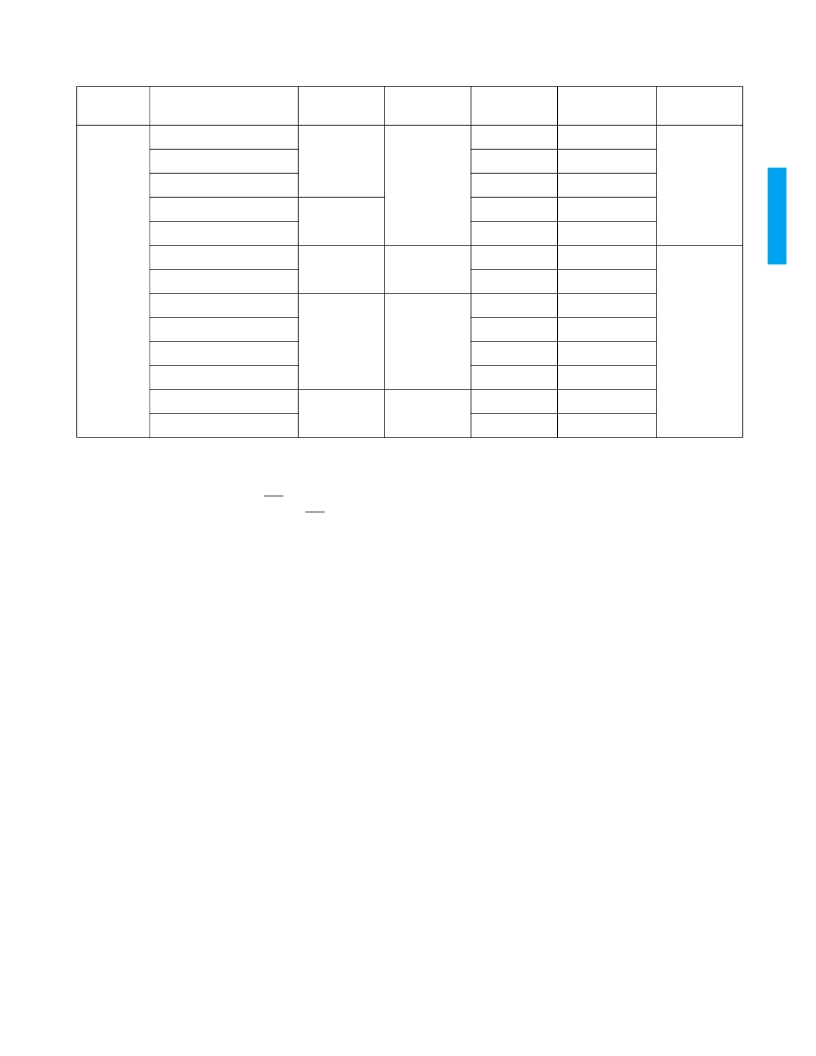
TABLE 4 SWITCH LINE POSITION FOR DIGITAL SYSTEMS (CONTINUED)
SYSTEM
VIDEO FORMAT
SAMPLING
SIGNAL
STANDARD
PARALLEL
INTERFACE
SERIAL
INTERFACE
SWITCH LINE
NO.
相關PDF資料 |
PDF描述 |
|---|---|
| GS15T48-5 | 15W DC-DC CONVERTER |
| GS15T48 | |
| GS15T5-5.2 | DC-to-DC Voltage Converter |
| GS15T5-52 | 15W DC-DC CONVERTER FOR ECL |
| GS175T48-12 | 120W/175W DC-DC CONVERTERS FAMILY |
相關代理商/技術參數(shù) |
參數(shù)描述 |
|---|---|
| GS1561-CF | 制造商:Rochester Electronics LLC 功能描述: 制造商:Gennum Corporation 功能描述: |
| GS1561-CFE3 | 制造商:Semtech Corporation 功能描述:Receiver for HD/SD/ASI w/out loop thru |
| GS1561-CFT | 制造商:Rochester Electronics LLC 功能描述: 制造商:Gennum Corporation 功能描述: |
| GS1561-CFTE3 | 制造商:Semtech Corporation 功能描述:Receiver for HD/SD/ASI w/out loop thru |
發(fā)布緊急采購,3分鐘左右您將得到回復。