- 您現(xiàn)在的位置:買賣IC網(wǎng) > PDF目錄299159 > GLT4160L04E-60J3 (Electronic Theatre Controls, Inc.) 4M X 4 CMOS DYNAMIC RAM WITH EXTENDED DATA OUTPUT PDF資料下載
參數(shù)資料
| 型號(hào): | GLT4160L04E-60J3 |
| 廠商: | Electronic Theatre Controls, Inc. |
| 英文描述: | 4M X 4 CMOS DYNAMIC RAM WITH EXTENDED DATA OUTPUT |
| 中文描述: | 4米× 4 CMOS動(dòng)態(tài)RAM的擴(kuò)展數(shù)據(jù)輸出 |
| 文件頁(yè)數(shù): | 18/22頁(yè) |
| 文件大?。?/td> | 588K |
| 代理商: | GLT4160L04E-60J3 |
第1頁(yè)第2頁(yè)第3頁(yè)第4頁(yè)第5頁(yè)第6頁(yè)第7頁(yè)第8頁(yè)第9頁(yè)第10頁(yè)第11頁(yè)第12頁(yè)第13頁(yè)第14頁(yè)第15頁(yè)第16頁(yè)第17頁(yè)當(dāng)前第18頁(yè)第19頁(yè)第20頁(yè)第21頁(yè)第22頁(yè)
G -LINK
GLT4160L04
4M X 4 CMOS DYNAMIC RAM WITH EXTENDED DATA OUTPUT
May 2001 (Rev.3.1)
G-Link Technology
2701 Northwestern Parkway
Santa Clara, CA 95051, U.S.A.
G-Link Technology Corporation,Taiwan
6F, No. 24-2, Industry E. RD, IV, Science Based
Industrial Park, Hsin Chu, Taiwan.
- 5 -
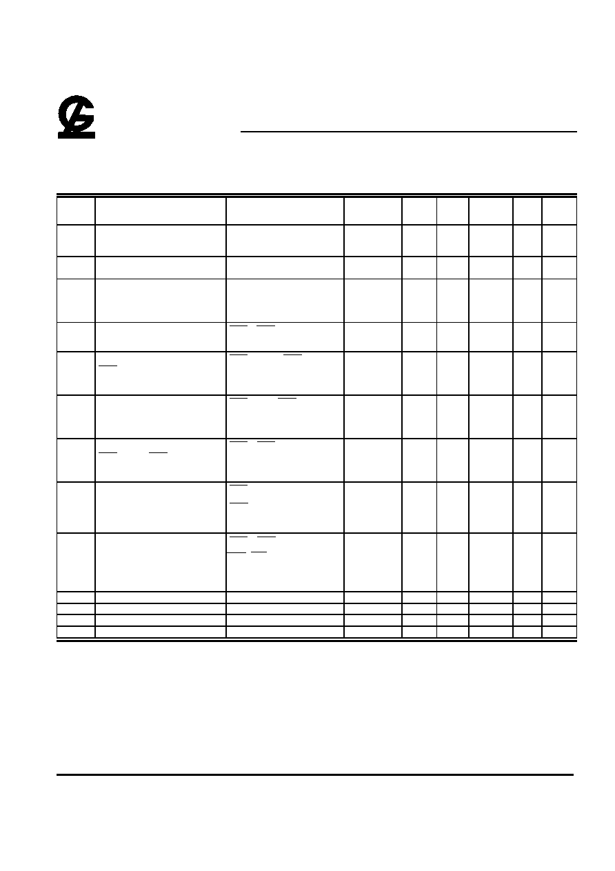
DC and Operating Characteristics (1-2)
TA = 0
°C to 70°C, -20°C to 85°C V
CC=3.3V
±0.3V, V
SS=0V, unless otherwise specified.
Sym.
Parameter
Test Conditions
Access
Time
Min.
Typ
Max.
Unit Notes
ILI
Input Leakage Current
(any input pin)
0V
≤ V
IN
≤ V
CC+0.3V
(All other pins not under
test=0V)
-5
+5
A
ILO
Output Leakage Current
(for High-Z State)
0V
≤ V
out
≤ V
CC
Output is disabled (Hiz)
-5
+5
A
ICC1
Operating Current,
Random READ/WRITE
tRC = tRC (min.)
tRAC = 40ns
tRAC = 50ns
tRAC = 60ns
tRAC = 70ns
130
120
80
70
mA
1,2
ICC2
Standby Current (TTL)
RAS , CAS at V
IH
other inputs
≥V
SS
1
mA
ICC3
Refresh Current,
RAS -Only
RAS cycling, CAS at V
IH
tRC = tRC (min.)
tRAC = 40ns
tRAC = 50ns
tRAC = 60ns
tRAC = 70ns
130
120
80
70
mA
2
ICC4
Operating Current,
EDO Page Mode
RAS at V
IL, CAS address
cycling:tPC=tPC(min.)
tRAC = 40ns
tRAC = 50ns
tRAC = 60ns
tRAC = 70ns
130
120
80
70
mA
1,2
ICC5
Refresh Current,
CAS Before RAS
RAS , CAS address cycling:
tRC=tRC (min.)
tRAC = 40ns
tRAC = 50ns
tRAC = 60ns
tRAC = 70ns
130
120
80
70
mA
1
ICC6
Standby Current, (CMOS)
RAS
≥V
CC-0.2V,
CAS
≥V
CC-0.2V,
All other inputs VSS
300
A
1,5
ICC7
Self refresh Current
RAS = CAS =0.2V,
WE = OE = A0~A10=VCC-0.2V or
0.2V
DQ0~DQ3=VCC-0.2V,0.2V or
Open
300
A
VIL
Input Low Voltage
-0.3
+0.8
V
3
VIH
Input High Voltage
2.0
VCC+0.3
V
4
VOL
Output Low Voltage
IOL = 2mA
0.4
V
VOH
Output High Voltage
IOH = -2mA
2.4
V
Notes:
1. ICC is dependent on output loading when the device output is selected. Specified ICC(max.) is measured with the output open.
2. ICC is dependent upon the number of address transitions specified ICC(max.) is measured with a maximum of one transition per address cycle
in random Read/Write and EDO Fast Page Mode.
3. Specified VIL(min.) is steady state operation. During transitions VIL(min.) may undershoot to –1V for a period not to exceed 15ns. All AC
parameters are measured with VIL(min.)
≥V
SS and VIH(max.)
≤V
CC.
4. Specified VIH(max.) is steady state operation . During transitions VIH(max.) may overshoot to VCC+1V for a period not to exceed 15ns. All AC
parameters are measured with VIL(min.)
≥ V
SS and VIH(max.)
≤ V
CC .
5. S-Version.
相關(guān)PDF資料 |
PDF描述 |
|---|---|
| GLT4160L04E-60TC | 4M X 4 CMOS DYNAMIC RAM WITH EXTENDED DATA OUTPUT |
| GLT4160L04E-70J3 | 4M X 4 CMOS DYNAMIC RAM WITH EXTENDED DATA OUTPUT |
| GLT4160L04E-70TC | 4M X 4 CMOS DYNAMIC RAM WITH EXTENDED DATA OUTPUT |
| GLT4160L04S-40J3 | 4M X 4 CMOS DYNAMIC RAM WITH EXTENDED DATA OUTPUT |
| GLT4160L04S-40TC | 4M X 4 CMOS DYNAMIC RAM WITH EXTENDED DATA OUTPUT |
相關(guān)代理商/技術(shù)參數(shù) |
參數(shù)描述 |
|---|---|
| GLT4160L04E-60TC | 制造商:未知廠家 制造商全稱:未知廠家 功能描述:4M X 4 CMOS DYNAMIC RAM WITH EXTENDED DATA OUTPUT |
| GLT4160L04E-70J3 | 制造商:未知廠家 制造商全稱:未知廠家 功能描述:4M X 4 CMOS DYNAMIC RAM WITH EXTENDED DATA OUTPUT |
| GLT4160L04E-70TC | 制造商:未知廠家 制造商全稱:未知廠家 功能描述:4M X 4 CMOS DYNAMIC RAM WITH EXTENDED DATA OUTPUT |
| GLT4160L04S-40J3 | 制造商:未知廠家 制造商全稱:未知廠家 功能描述:4M X 4 CMOS DYNAMIC RAM WITH EXTENDED DATA OUTPUT |
| GLT4160L04S-40TC | 制造商:未知廠家 制造商全稱:未知廠家 功能描述:4M X 4 CMOS DYNAMIC RAM WITH EXTENDED DATA OUTPUT |
發(fā)布緊急采購(gòu),3分鐘左右您將得到回復(fù)。