- 您現(xiàn)在的位置:買賣IC網(wǎng) > PDF目錄384322 > GB3212 (Gennum Corporation) DUET⑩ DIGITAL Advanced DSP System with FRONTWAVE㈢ PDF資料下載
參數(shù)資料
| 型號(hào): | GB3212 |
| 廠商: | Gennum Corporation |
| 英文描述: | DUET⑩ DIGITAL Advanced DSP System with FRONTWAVE㈢ |
| 中文描述: | 二重奏⑩先進(jìn)的DSP數(shù)字系統(tǒng)的FRONTWAVE㈢ |
| 文件頁(yè)數(shù): | 8/10頁(yè) |
| 文件大小: | 118K |
| 代理商: | GB3212 |
GENNUM CORPORATION
20352 - 2
8 of 10
G
Static Switch on MS1 Static Switch on MS2 (jump to memory D)
This mode uses two static switches to change memories.
Unlike in the previous example, this mode will switch to
memory D when the static switch on MS2 is OPEN. This
means that this mode will only use a maximum of three
memories (even if four valid memories are programmed).
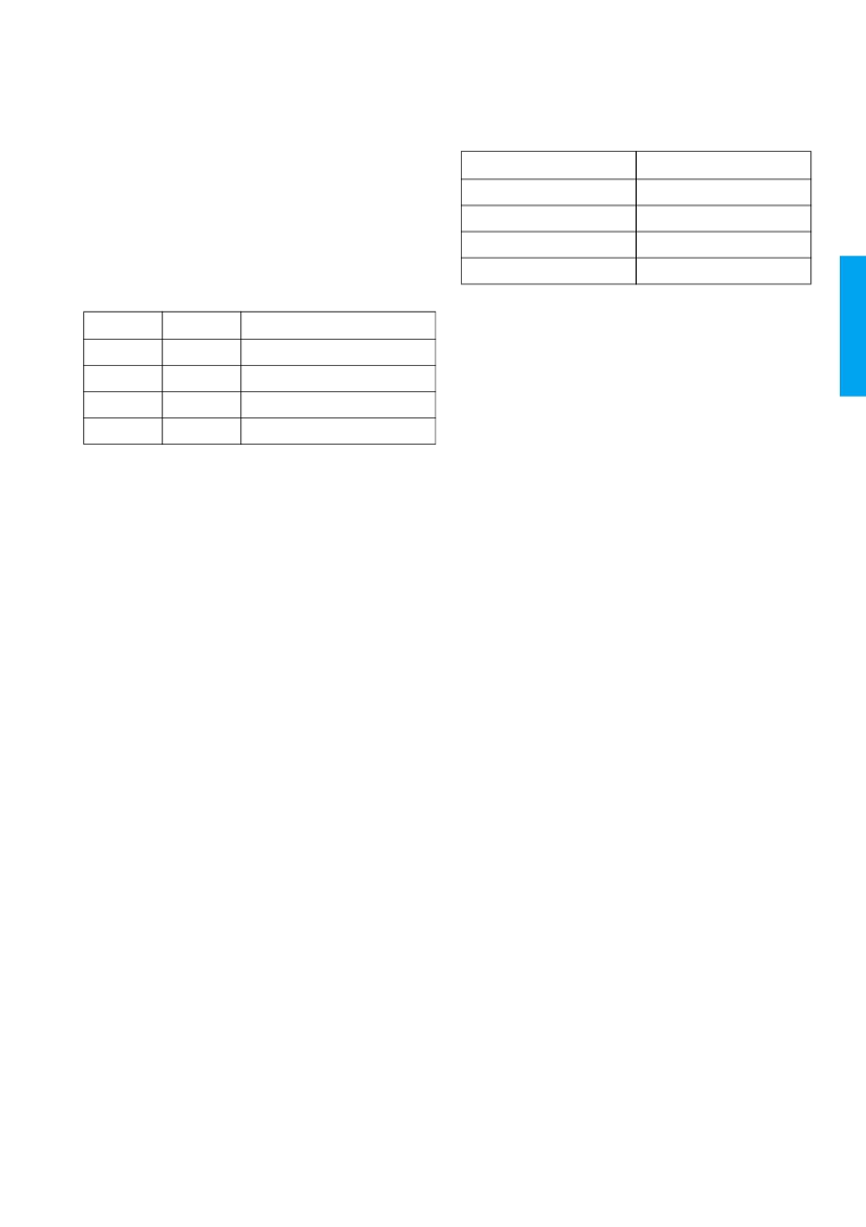
The following table describes which memory is selected
depending on the state of the switches.
In this mode it is possible to jump from any memory to any
other memory simply by changing the state of both
switches. If both switches are changed simultaneously then
the transition will be smooth, otherwise, if one switch is
changed and then the other, the part will transition to an
intermediate memory before reaching the final memory.
The part will start in whatever memory the switches are
selecting. If the device starts up in a memory other than A,
and the memory beep tones are enabled, the device will
emit the corresponding tones for that memory. If a memory
is invalid and the part starts up with the switches indicating
this memory, the part will stay in memory A.
AUDIBLE MEMORY CHANGE INDICATOR
The DUET DIGITAL can be programmed to produce
tones to indicate a memory change. Using the Interactive
Data Sheet the GB3212 can be configured to either enable
or disable the Memory Change Indicator.
When the Memory Change Indicator is enabled, there is an
option to have a single beep for each memory change or
multiple beeps.
The amplitude and frequency of the memory change tone
can be selected independent of the Tone Generator
settings and can be individually selected for each memory.
When the memory change multiple beep is enabled and the
memory change tone is enabled, then during a memory
change operation the selected tone will beep a code to
indicate which memory has been selected. The beep
sequence will be 150ms ON followed by a 150ms OFF time
between the beeps. The memory change beeping code is
deciphered in the table below.
TONE GENERATOR
The programmable tone generator is capable of producing
programmable tones. Upon reception of the tone enable
instruction, the DUET DIGITAL connects the output of the
tone generator to the input of the D/A converter. The
programmed tone is then output until a tone disable
instruction is issued. When disabled, the normal audio
signal is again connected.
WIDE DYNAMIC RANGE COMPRESSION
Any combination of adjacent frequency bands can be
grouped
to
form
four
compression. The I/O curve of each channel is divided into
up to four regions (linear, compression, return to linear,
clipping). The thresholds between these regions are
adjustable over a wide range. Each channel has twin
average detectors: a fast detector with a configurable time
constant and a slow detector with a configurable time
constant.
independent
channels
of
FREQUENCY SHAPING
The 16-band signal processor acts as a graphic equalizer.
The gain of each band can be adjusted over 0 to -42dB
range. The width of each band is 500Hz. The bands can be
selected to have either an even or odd stacking
arrangement. Selecting even stacking shifts the bands in
unison by one half-band width (250Hz) effectively doubling
the number of potential band edges. The default setting will
be even stacking as this effectively results in one "extra"
band since the nyquist band is "split" into two 250Hz bands,
one from 0 to 250Hz the other from 7750Hz to 8000Hz.
MS1
MS2
Memory
LOW
LOW
A
LOW
OPEN
D if valid otherwise no change)
OPEN
LOW
B (if valid otherwise no change)
OPEN
OPEN
D (if valid otherwise no change)
SELECTED MEMORY
# OF BEEPS
A
1
B
2
C
3
D
4
相關(guān)PDF資料 |
PDF描述 |
|---|---|
| GB3221 | Power PARAGON-TM DIGITAL Four Channel DSP System with FRONTWAVE-R |
| GB3225 | PARAGON⑩ DIGITAL Four Channel DSP System with FRONTWAVE |
| GBI10A | Silicon-Bridge Rectifiers |
| GBI10B | Silicon-Bridge Rectifiers |
| GBI10D | Silicon-Bridge Rectifiers |
相關(guān)代理商/技術(shù)參數(shù) |
參數(shù)描述 |
|---|---|
| GB3215 | 制造商:GENNUM 制造商全稱:GENNUM 功能描述:PARAGON⑩ DIGITAL Four Channel DSP System with FRONTWAVE |
| GB3216TC-DPG | 制造商:YSTONE 制造商全稱:Yellow Stone Corp 功能描述:CERAMIC BASIC TYPE HIGH-PERFORMANCE LEDS |
| GB3221 | 制造商:GENNUM 制造商全稱:GENNUM 功能描述:Power PARAGON-TM DIGITAL Four Channel DSP System with FRONTWAVE-R |
| GB3225 | 制造商:GENNUM 制造商全稱:GENNUM 功能描述:PARAGON⑩ DIGITAL Four Channel DSP System with FRONTWAVE |
| GB-323 | 制造商:LUCKY-LIGHT 制造商全稱:LUCKY-LIGHT 功能描述:Round Type Low Profile LED Lamps (4.7mm) |
發(fā)布緊急采購(gòu),3分鐘左右您將得到回復(fù)。