- 您現(xiàn)在的位置:買(mǎi)賣(mài)IC網(wǎng) > PDF目錄384323 > GB3221 (Gennum Corporation) Power PARAGON-TM DIGITAL Four Channel DSP System with FRONTWAVE-R PDF資料下載
參數(shù)資料
| 型號(hào): | GB3221 |
| 廠商: | Gennum Corporation |
| 英文描述: | Power PARAGON-TM DIGITAL Four Channel DSP System with FRONTWAVE-R |
| 中文描述: | Power Paragon的- TM數(shù)字四通道的DSP系統(tǒng)的FRONTWAVE受體 |
| 文件頁(yè)數(shù): | 1/7頁(yè) |
| 文件大小: | 91K |
| 代理商: | GB3221 |
GB3211/GB3221 PRELIMINARY DATA SHEET
Doc.No.20475 - 4 [Rev. December 2003]
1 of 7
G
FEATURES
high power applications
highly configurable, versatile DSP platform
high fidelity multi-channel AGC signal processing
95dB input dynamic range with HRX Headroom
Extension
fully programmable via serial data interface
high performance data converters – dual, over-
sampled A/Ds; over-sampled D/A with efficient
switched-mode output power amp
SOUND
DESIGN
high-fidelity audio quality
drives zero-bias 2-terminal receivers
multiple communication rates up to 85.3kb/s
multi-memory
internal/external volume control
volume control taper determined by external VC
2 memory select pads
tri-state memory select operation
audible memory change indicator
thinSTAX
PACKAGING
Hybrid typical dimensions:
0.227 x 0.125 x 0.060 in
(5.76 x 3.18 x 1.52 mm)
DESCRIPTION
The GB3211 (GB3221) hybrid is a programmable DSP
system based on a multi-channel compression circuit. This
hybrid is designed for low impedance receivers. It can be
used as a platform for a wide range of hearing aid
applications. It also offers a seperate supply line to the A/D
and
H-Bridge
circuits.
The
packaging enables easy integration into BTE applications.
This versatile DSP hybrid is capable of multiple
configurations and has a wide range of functions.
reflowable
thinSTAX
The GB3211 hybrid contains the GC5051 controller chip
and the GB3221 hybrid contains the GC5057 controller
chip. The only difference between the GC5051 and the
GC5057 is in their Power On Reset (POR) behaviour.
For a detailed description of the POR behaviour of the
GC5051 and GC5057 controller chips, please refer to
PARAGON
DIGITAL
Reference
#20143.
Guide
,
Document
The GB3211 and the GB3221 hybrid code programmed
into the GC5051 and the GC5057 controller chips is “7”.
This data sheet is a part of a set of documents available for
this product. Please refer to
Getting Started with
PARAGON DIGITAL
” information note for a list of other
documents.
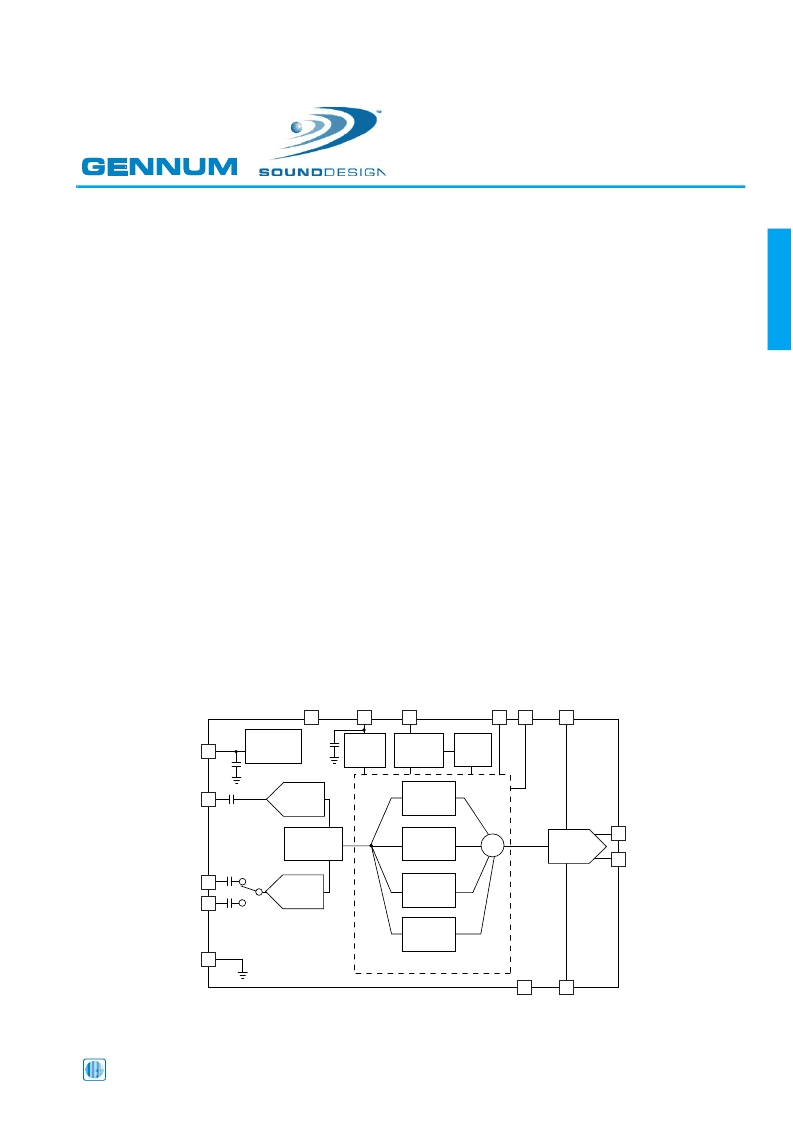
BLOCK DIAGRAM
PGND
FMIC
MGND
VREG
RMIC
T
VC
5
OUT-
OUT+
MS
11
SDA
4
VB
12
INTERFACE
VC
A/D
FRONTWAVE
CHANNEL 1
CHANNEL 2
CHANNEL 3
CHANNEL 4
EEPROM
REGULATOR
GB3211
(GB3221)
A/D
A/D
D/A
HBRIDGE
205n
60n
13n
70n
70n
All resistors in ohms, all capacitors in farads unless otherwise stated.
S
MS2
13
VBP
14
GND
8
10
6
9
7
15
1
2
3
Power PARAGON
DIGITAL
Four Channel
DSP System
with
F
RONT
W
AVE
相關(guān)PDF資料 |
PDF描述 |
|---|---|
| GB3225 | PARAGON⑩ DIGITAL Four Channel DSP System with FRONTWAVE |
| GBI10A | Silicon-Bridge Rectifiers |
| GBI10B | Silicon-Bridge Rectifiers |
| GBI10D | Silicon-Bridge Rectifiers |
| GBI10G | Silicon-Bridge Rectifiers |
相關(guān)代理商/技術(shù)參數(shù) |
參數(shù)描述 |
|---|---|
| GB3225 | 制造商:GENNUM 制造商全稱:GENNUM 功能描述:PARAGON⑩ DIGITAL Four Channel DSP System with FRONTWAVE |
| GB-323 | 制造商:LUCKY-LIGHT 制造商全稱:LUCKY-LIGHT 功能描述:Round Type Low Profile LED Lamps (4.7mm) |
| GB-323GD | 制造商:LUCKY-LIGHT 制造商全稱:LUCKY-LIGHT 功能描述:Round Type Low Profile LED Lamps (4.7mm) |
| GB-323GT | 制造商:LUCKY-LIGHT 制造商全稱:LUCKY-LIGHT 功能描述:Round Type Low Profile LED Lamps (4.7mm) |
| GB-323HD | 制造商:LUCKY-LIGHT 制造商全稱:LUCKY-LIGHT 功能描述:Round Type Low Profile LED Lamps (4.7mm) |
發(fā)布緊急采購(gòu),3分鐘左右您將得到回復(fù)。