- 您現(xiàn)在的位置:買賣IC網(wǎng) > PDF目錄375797 > FIC03272 (Electronic Theatre Controls, Inc.) Microprocessor for handling signals from the TGS4161 carbon dioxide sensor PDF資料下載
參數(shù)資料
| 型號(hào): | FIC03272 |
| 廠商: | Electronic Theatre Controls, Inc. |
| 英文描述: | Microprocessor for handling signals from the TGS4161 carbon dioxide sensor |
| 中文描述: | 微處理器處理的TGS4161二氧化碳傳感器信號(hào) |
| 文件頁(yè)數(shù): | 5/14頁(yè) |
| 文件大小: | 366K |
| 代理商: | FIC03272 |
第1頁(yè)第2頁(yè)第3頁(yè)第4頁(yè)當(dāng)前第5頁(yè)第6頁(yè)第7頁(yè)第8頁(yè)第9頁(yè)第10頁(yè)第11頁(yè)第12頁(yè)第13頁(yè)第14頁(yè)

Revised 06/04
5
TECHNICAL INFORMATION FOR FIC03272
4-1-3
Input signal Tr for automatic benchmark reset (Pin
No. 13)
Whenever the benchmark level Vg has only been
adjusted (
Sec. 4-1-2
) and has not been renewed (
Sec.
1-1
) for a pre-set period of time (Tr), it should be auto-
matically reset at the current output signal in ambient
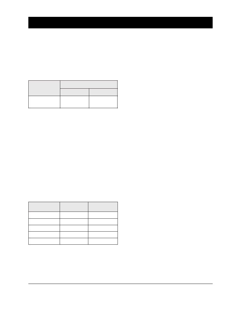
air. Table 4 shows the time intervals (Tr) which can
be pre-set by applying a signal to Port R52.
4-1-4
Input signal for damper control (Pin No. 9)
Concentration levels of CO
2
at which the damper
control signals are activated are selected by inputting
a voltage signal to port A
IN2
. Sensor output voltage
is first AD converted within the microprocessor. The
relationship between these AD converted values and
CO
2
concentrations is shown in Table 5. Whenever a
CO
2
concentration exceeds the threshold level for
opening the damper (Cd1), a low signal (L) is output
from port R60. A high signal (H) is output for closing
the damper when the CO
2
concentration drops
beneath the Cd2 level. Figure 11 shows the circuit
for damper control signal threshold. Please note that
a high signal (H) is designed to be output during the
sensor’s initial warm-up period and also whenever
the malfunction signal is activated.
4-2
Gas sensor signal Vg input (Pin No. 7)
Since the raw sensor output voltage (EMF) actually
decreases as CO
2
concentration increases, the sensor’s
output voltage is reversed, amplified and adjusted
(please refer to Figure 3,
Sec. 4-4
, and
Sec. 5-1
for
details). The result of this process is a gas sensor signal
Vg with good resolution and which increases/
decreases as CO
2
concentration increases/decreases.
This gas sensor signal Vg is input to port AIN0.
4-3
Thermistor signal V
T
input (Pin No. 8)
To compensate for the temperature dependency of
CO
2
sensor, a signal from an external thermistor (V
T
)
is input to port AIN1.
4-4
Bias signal output (Pin No. 24)
A PWM signal, of which the pulse width is variable,
is output from port R90. To optimize the resolution
of Vg readings, this signal is introduced to the
differential circuit after being converted to an analog
voltage, and adjusts the benchmark level Vg to fall
between 25 and 51 counts at AD converted value, or
0.38 ~ 0.75V at 3.8V full scale. The bias signal starts
from 128 counts (1.9V at 3.8V full scale) when the
power is switched on, and reduces the count stepwise
along with the sensor’s initial action until Vg falls
and then stabilizes at the above stated level.
4-5
Manual benchmark reset signal input (Pin No. 27)
The benchmark level can be reset manually at any
time by inputting an “L” pulse to port KEO. This
manual benchmark reset should be done in a clean
atmosphere where the CO
2
concentration is about
400ppm (please refer to
Sec. 5-6 - Benchmark reset
circuit
).
Note: If the benchmark level is manually reset under
a high CO
2
concentration environment, the device’s
sensitivity would be decreased and calculated CO
2
concentration values would be less than the actual
concentration.
4-6
Sensor signal output
4-6-1
PWM signal output for CO
2
concentration (Pin No. 25)
A PWM signal is output from port R91 to show CO
2
g
n
S
t
p
n
I
l
n
g
"
H
"
"
L
"
e
m
i
)
T
(
o
A
s
a
d
7
s
a
d
0
3
Table 4 - Auto reset timer setting (AM-4-4161 default = 7 days)
t
p
2
n
n
e
v
n
g
c
D
)
5
5
:
o
A
(
)
m
p
p
1
d
C
)
m
p
p
2
d
C
8
4
-
0
0
0
8
0
2
7
6
9
-
9
4
0
0
0
1
0
0
8
4
4
1
-
7
9
0
0
5
1
0
0
3
1
2
9
1
-
5
4
1
0
0
0
2
0
0
8
1
5
5
2
-
3
9
1
0
0
0
3
0
0
7
2
Table 5 - Thresholds for damper OPEN/CLOSE signal
Cd1: Threshold for OPEN signal
Cd2: Threshold for CLOSE signal
* 8-bit - Least significant byte=3.8V/256
相關(guān)PDF資料 |
PDF描述 |
|---|---|
| FID-550 | Resistive Touch Panel Specification |
| FID3Z1KX | 320 x 240 pixel format, LED or CFL Backlight |
| FID3Z1LX | 320 x 240 pixel format, LED or CFL Backlight |
| FID3Z2KX | 122 x 32 pixel format, Compact LCD size |
| FID3Z2LX | 122 x 32 pixel format, Compact LCD size |
相關(guān)代理商/技術(shù)參數(shù) |
參數(shù)描述 |
|---|---|
| FIC04G-60 | 制造商:AXIOMTEK 制造商全稱:AXIOMTEK 功能描述:Anti-vibration & shock resistance |
| FIC08G-60 | 制造商:AXIOMTEK 制造商全稱:AXIOMTEK 功能描述:Anti-vibration & shock resistance |
| FIC128-60 | 制造商:AXIOMTEK 制造商全稱:AXIOMTEK 功能描述:Anti-vibration & shock resistance |
| FIC16G-60 | 制造商:AXIOMTEK 制造商全稱:AXIOMTEK 功能描述:Anti-vibration & shock resistance |
| FIC-200 | 功能描述:安全/ 驗(yàn)證開發(fā)工具 PC Card Type II Fingerprint Reader RoHS:否 制造商:Digi International 產(chǎn)品:Development Kits 工具用于評(píng)估:XEB-AW140 接口類型:SPI, USB 工作電源電壓:3.1 V to 3.6 V |
發(fā)布緊急采購(gòu),3分鐘左右您將得到回復(fù)。