- 您現(xiàn)在的位置:買賣IC網(wǎng) > PDF目錄375704 > F3D480M20A (Vicor Corporation) VI Chip PFM Power Factor Module PDF資料下載
參數(shù)資料
| 型號: | F3D480M20A |
| 廠商: | Vicor Corporation |
| 元件分類: | 基準電壓源/電流源 |
| 英文描述: | VI Chip PFM Power Factor Module |
| 中文描述: | 六烤瓷芯片功率因數(shù)模塊 |
| 文件頁數(shù): | 4/14頁 |
| 文件大小: | 457K |
| 代理商: | F3D480M20A |

Vicor Corporation
Tel: 800-735-6200
vicorpower.com
Power Factor Module
F3D480T20A
Rev. 1.0
Page 4 of 14
PRELIMINARY
Primary side
+IN / -IN – DC voltage
The PFM operates from a full wave rectified AC voltage within the
limits shown on page 2. PFMs have internal over / undervoltage
lockout functions that prevent operation outside of the specified rms
input range. PFMs will turn on when the input voltage rises above its
undervoltage lockout. If the input voltage exceeds the overvoltage
lockout, PFMs will shut down until the overvoltage fault clears.
BV - bias voltage
A 47 μF 50 V electrolytic capacitor must be connected between this
port and –IN to provide energy storage for the primary bias circuit.
RSV – reserved
PC – primary control
The PFM voltage output is enabled when the PC pin is open circuit
(floating). To disable the PFM output voltage, the PC pin is pulled to
–IN. Open collector optocouplers, transistors, or relays can be used to
control the PC pin. When using multiple PFMs in a high power array,
the PC ports should be tied together to synchronize their turn on.
Secondary side
DC+
A hold-up capacitor should be connected between this port and SG
to provide output hold-up in the event of an input power failure.
For 10 ms hold-up at full load, a 2,200 μF 50 V electrolytic capacitor
is recommended. DC+ should not be back driven.
PR – parallel port
(analog control models only)
The PR port signal, which is proportional to the PFM output power,
supports current sharing among PFMs. To enable current sharing, PR
ports should be interconnected. No bypass capacitance should be used
when interconnecting PR ports and steps should be taken to minimize
stray capacitance and noise coupling into this line (e.g, by minimizing
the width of PR port interconnect traces that lay over, or in proximity
to, signal grounds or power / ground planes). The PR port is referenced
to SG.
Pin/Control Functions
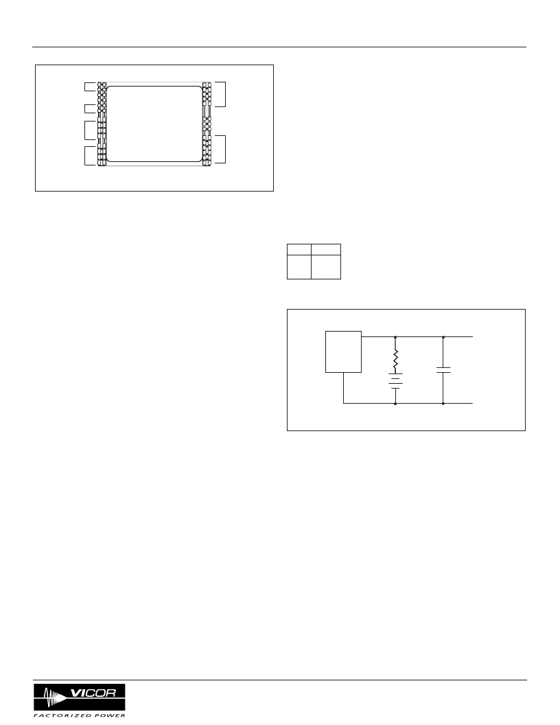
BOTTOM VIEW
+OUT
-OUT
+IN
B V
RSV
PC
-IN
Power Factor Module (PFM)
DC+
PR
SC
SG
SC – secondary control
(analog control models only)
The output voltage may be programmed, margined or trimmed down
by connecting a voltage source or resistor between the SC port and SG
port. The slew rate of the output voltage may be reduced by controlling
the rate-of-rise for the voltage at the SC port ( e.g. to limit inrush into a
capacitive load).
The following expression should be used to calculate the required set
point resistor value. No resistor is required if the user desires a nominal
48 V output.
R = ( Vo / (48 - Vo) ) 30.1 k
Ω
Where: R = the set point resistor
Vo = the desired output voltage set point
Example:
Vo R
42 V 211 k
Ω
36 V 90.3 k
Ω
SG – signal return
(analog control models only)
This port should be used as reference for the SC, PR, and DC+ ports.
Care must be taken to insure there are no low impedance paths
between -OUT and SG. Such a path could allow current to bypass the
internal current sense resistor.
+ OUT / -OUT – voltage output
These ports provide the isolated DC output voltage. The –OUT pin is
separated from the SG (Signal Return) pin by the internal current
sensing resistor.
Safety consideration
Care must be exercised to insure appropriate spacing, clearance and
creepage distances are maintained between line side terminals and
secondary SELV terminals.
μ
P
1 nF
ref
1.25 V
1.25 V
Full Scale
SC
SG
30.1 k
Ω
Figure 2
—Functional block diagram
Figure 1
— PFM pin out
Table 1
相關(guān)PDF資料 |
PDF描述 |
|---|---|
| F3D480T20A | VI Chip PFM Power Factor Module |
| F3S49092 | 20A/10A, 12V, 0.060/0.140 Ohm, Logic Level, Complementary Power MOSFET |
| F40UP20DN | Ultrafast Recovery Power Rectifier |
| F4294-09 | MCP ASSEMBLY WITH CENTER HOLE FOR REFLECTRON MS |
| F43KU | High Voltage Thick Film Resistors |
相關(guān)代理商/技術(shù)參數(shù) |
參數(shù)描述 |
|---|---|
| F3D480T20A | 制造商:VICOR 制造商全稱:Vicor Corporation 功能描述:VI Chip PFM Power Factor Module |
| F3DB-14474-AA | 制造商:Ford Motor Company 功能描述:Female Metri-Pack 480 Tin Plated Terminal, Cable Range 2.50 - 1.00 mm2, Cable Insulation Range 3.59 - 2.56 mm |
| F3DB-14474-BA | 制造商:Ford Motor Company 功能描述:Female Metri-Pack 480 Tin Plated Terminal, Cable Range 1.00 - 0.50 mm2, Cable Insulation Range 2.68 - 2.11 mm |
| F3DB-14474-CA | 制造商:Ford Motor Company 功能描述:Female Metri-Pack 480 Tin Plated Terminal, Cable Range 5.00 - 3.00 mm2, Cable Insulation Range 5.24 - 3.49 mm |
| F3E3 | 制造商:EDAL 制造商全稱:EDAL 功能描述:Silicon Power Rectifiers |
發(fā)布緊急采購,3分鐘左右您將得到回復。