- 您現在的位置:買賣IC網 > PDF目錄97868 > DS2432P/T&R (MAXIM INTEGRATED PRODUCTS INC) 1K X 1 1-WIRE SERIAL EEPROM, PDSO6 PDF資料下載
參數資料
| 型號: | DS2432P/T&R |
| 廠商: | MAXIM INTEGRATED PRODUCTS INC |
| 元件分類: | Programmable ROM |
| 英文描述: | 1K X 1 1-WIRE SERIAL EEPROM, PDSO6 |
| 封裝: | 0.150 INCH, TSOC-6 |
| 文件頁數: | 13/16頁 |
| 文件大小: | 168K |
| 代理商: | DS2432P/T&R |
Abridged Data Sheet
DS2432
6 of 14
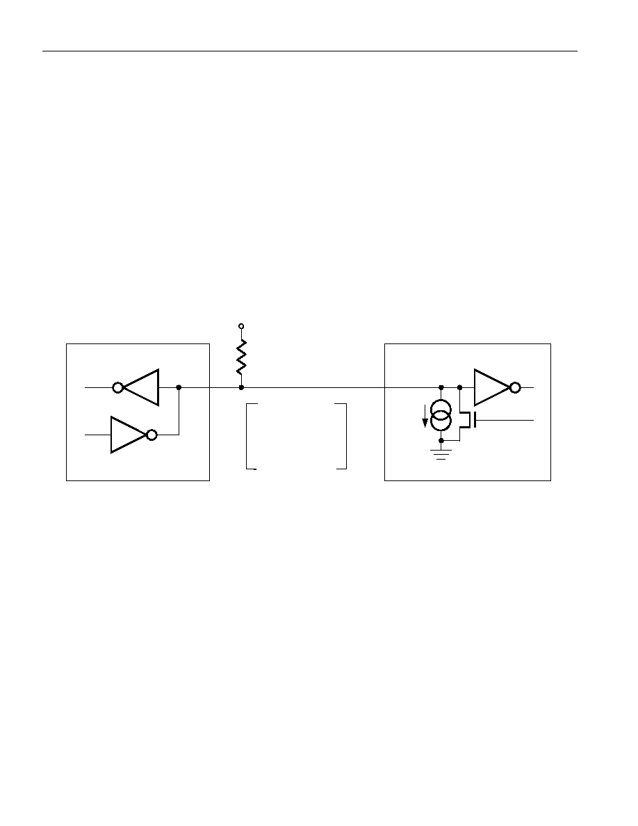
HARDWARE CONFIGURATION
The 1-Wire bus has only a single line by definition; it is important that each device on the bus be able to
drive it at the appropriate time. To facilitate this, each device attached to the 1-Wire bus must have open
drain or 3-state outputs. The 1-Wire port of the DS2432 is open drain with an internal circuit equivalent
to that shown in Figure 8. A multidrop bus consists of a 1-Wire bus with multiple slaves attached. At
regular speed the 1-Wire bus has a maximum data rate of 16.3k bits per second. The speed can be boosted
to 142k bits per second by activating the Overdrive Mode. The DS2432 requires a 1-Wire pull-up resistor
of maximum 2.2 k
Ω for executing any of its memory and SHA function commands at any speed. When
communicating with several DS2432 simultaneously, e. g., to install the same secret in several devices,
the resistor should be bypassed by a low-impedance pull-up to VPUP while the device transfers data from
the scratchpad to the EEPROM and updates the tamper-detect register.
The idle state for the 1-Wire bus is high. If for any reason a transaction needs to be suspended, the bus
MUST be left in the idle state if the transaction is to resume. If this does not occur and the bus is left low
for more than 16 s (Overdrive Speed) or more than 120 s (regular speed), one or more devices on the
bus may be reset.
HARDWARE CONFIGURATION Figure 8
Open Drain
Port Pin
RX = RECEIVE
TX = TRANSMIT
100
Ω
MOSFET
VPUP
RX
TX
RX
DATA
RPU
5 A
Typ.
BUS MASTER
DS2432 1-Wire PORT
TRANSACTION SEQUENCE
The protocol for accessing the DS2432 via the 1-Wire port is as follows:
Initialization
ROM Function Command
Memory or SHA Function Command
Transaction/Data
INITIALIZATION
All transactions on the 1-Wire bus begin with an initialization sequence. The initialization sequence
consists of a reset pulse transmitted by the bus master followed by presence pulse(s) transmitted by the
slave(s). The presence pulse lets the bus master know that the DS2432 is on the bus and is ready to
operate. For more details, see the “1-Wire Signaling” section.
相關PDF資料 |
PDF描述 |
|---|---|
| DS2432X | 1K X 1 1-WIRE SERIAL EEPROM, PBGA6 |
| DS2432P | 1K X 1 1-WIRE SERIAL EEPROM, PDSO6 |
| DS2433 | 512 X 8 1-WIRE SERIAL EEPROM, PBCY3 |
| DS2433X | 4K X 1 1-WIRE SERIAL EEPROM, UUC2 |
| DS2433S | 512 X 8 1-WIRE SERIAL EEPROM, PDSO8 |
相關代理商/技術參數 |
參數描述 |
|---|---|
| DS2432P-W01+3T | 制造商:Maxim Integrated Products 功能描述:1KB PROTECTED 1-WIRE EEPROM WITH SHA-1 ENGINE - Tape and Reel |
| DS2432P-W0F+1T | 制造商:Maxim Integrated Products 功能描述: |
| DS2432Q-W01+4T | 制造商:Maxim Integrated Products 功能描述:1KB PROTECTED 1-WIRE EEPROM WITH SHA-1 E |
| DS2432X | 功能描述:電可擦除可編程只讀存儲器 RoHS:否 制造商:Atmel 存儲容量:2 Kbit 組織:256 B x 8 數據保留:100 yr 最大時鐘頻率:1000 KHz 最大工作電流:6 uA 工作電源電壓:1.7 V to 5.5 V 最大工作溫度:+ 85 C 安裝風格:SMD/SMT 封裝 / 箱體:SOIC-8 |
| DS2432X+ | 功能描述:電可擦除可編程只讀存儲器 RoHS:否 制造商:Atmel 存儲容量:2 Kbit 組織:256 B x 8 數據保留:100 yr 最大時鐘頻率:1000 KHz 最大工作電流:6 uA 工作電源電壓:1.7 V to 5.5 V 最大工作溫度:+ 85 C 安裝風格:SMD/SMT 封裝 / 箱體:SOIC-8 |
發(fā)布緊急采購,3分鐘左右您將得到回復。