- 您現(xiàn)在的位置:買賣IC網(wǎng) > PDF目錄97863 > DS1626U/T&R (MAXIM INTEGRATED PRODUCTS INC) DIGITAL TEMP SENSOR-SERIAL, 12BIT(s), 0.50Cel, RECTANGULAR, SURFACE MOUNT PDF資料下載
參數(shù)資料
| 型號: | DS1626U/T&R |
| 廠商: | MAXIM INTEGRATED PRODUCTS INC |
| 元件分類: | Switch/Digital Output Temperature Sensor |
| 英文描述: | DIGITAL TEMP SENSOR-SERIAL, 12BIT(s), 0.50Cel, RECTANGULAR, SURFACE MOUNT |
| 封裝: | MICRO, SOP-8 |
| 文件頁數(shù): | 12/12頁 |
| 文件大?。?/td> | 141K |
| 代理商: | DS1626U/T&R |
DS1626/DS1726
9 of 12
CONFIGURATION REGISTER
The configuration register allows the user to customize the DS1626/DS1726 conversion and thermostat
options. It also provides information to the user about conversion status, EEPROM activity, and
thermostat activity. The configuration register is arranged as shown in Figure 6 and detailed descriptions
of each bit are provided in Table 3. This register can be accessed using the Read Config and Write Config
commands. Note that the R1, R0, CPU, and 1SHOT bits are stored in EEPROM and all other
configuration register bits are SRAM.
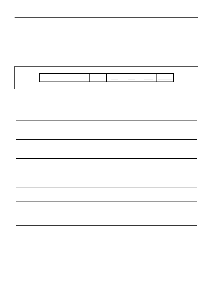
Figure 6. CONFIGURATION REGISTER
MSb
BIT 6
BIT 5
BIT 4
BIT 3
BIT 2
BIT 1
LSb
DONE
THF
TLF
NVB
R1*
R0*
CPU*
1SHOT*
*NV (EEPROM)
Table 3. CONFIGURATION REGISTER BIT DESCRIPTIONS
BIT NAME
(USER ACCESS)
FUNCTIONAL DESCRIPTION
DONE
(Read Only)
Power-up state = 1.
DONE = 0. Temperature conversion is in progress.
DONE = 1. Temperature conversion is complete.
THF
(Read/Write)
Power-up state = 0.
THF = 1. The measured temperature has reached or exceeded the value stored in the
TH register. THF will remain a 1 until it is overwritten with a 0 by the user, the
power is cycled, or a Software POR command is issued.
TLF
(Read/Write)
Power-up state = 0.
TLF = 1. The measured temperature has equaled or dropped below the value stored
in the TL register. TLF will remain a 1 until it is overwritten with a 0 by the user, the
power is cycled, or a Software POR command is issued.
NVB
(Read Only)
Power-up state = 0.
NVB = 1. Write to an E
2 memory cell is in progress.
NVB = 0. NV memory is not busy.
R1*
(Read/Write)
Power-up state = last value written to this bit.
Sets conversion resolution (see Table 4).
Initial state from factory = 1.
R0*
(Read/Write)
Power-up state = last value written to this bit.
Sets conversion resolution (see Table 4).
Initial state from factory = 1.
CPU*
(Read/Write)
Power-up state = last value written to this bit.
CPU = 1. Stand-alone mode is disabled.
CPU = 0. Stand-alone mode is enabled when
RST = 0. See CPU BIT AND STAND-
ALONE THERMOSTAT OPERATION section for more information.
Initial state from factory = 0.
1SHOT*
(Read/Write)
Power-up state = last value written to this bit.
1SHOT = 1: One-Shot Mode. The Start Convert T command initiates a single
temperature conversion and then the device goes into a low-power standby state.
1SHOT = 0: Continuous Conversion Mode. The Start Convert T command initiates
continuous temperature conversions.
Initial state from factory = 0.
*NV (EEPROM)
相關(guān)PDF資料 |
PDF描述 |
|---|---|
| DS1626U | DIGITAL TEMP SENSOR-SERIAL, 12BIT(s), 0.50Cel, RECTANGULAR, SURFACE MOUNT |
| DS1726U+ | DIGITAL TEMP SENSOR-SERIAL, 12BIT(s), 0.50Cel, RECTANGULAR, SURFACE MOUNT |
| DS17285E-3 | 1 TIMER(S), REAL TIME CLOCK, PDSO28 |
| DS17285E-5 | 1 TIMER(S), REAL TIME CLOCK, PDSO28 |
| DS17285S-5 | 1 TIMER(S), REAL TIME CLOCK, PDSO24 |
相關(guān)代理商/技術(shù)參數(shù) |
參數(shù)描述 |
|---|---|
| DS1628 | 制造商:NSC 制造商全稱:National Semiconductor 功能描述:Octal TRI-STATE MOS Drivers |
| DS1628J | 制造商:NSC 制造商全稱:National Semiconductor 功能描述:Octal TRI-STATE MOS Drivers |
| DS1628J/A+ | 制造商:未知廠家 制造商全稱:未知廠家 功能描述:Memory Driver |
| DS1629 | 制造商:DALLAS 制造商全稱:Dallas Semiconductor 功能描述:2-Wire Digital Thermometer and Real Time Clock |
| DS1629S | 功能描述:板上安裝溫度傳感器 RoHS:否 制造商:Omron Electronics 輸出類型:Digital 配置: 準(zhǔn)確性:+/- 1.5 C, +/- 3 C 溫度閾值: 數(shù)字輸出 - 總線接口:2-Wire, I2C, SMBus 電源電壓-最大:5.5 V 電源電壓-最小:4.5 V 最大工作溫度:+ 50 C 最小工作溫度:0 C 關(guān)閉: 安裝風(fēng)格: 封裝 / 箱體: 設(shè)備功能:Temperature and Humidity Sensor |
發(fā)布緊急采購,3分鐘左右您將得到回復(fù)。