- 您現(xiàn)在的位置:買賣IC網(wǎng) > PDF目錄97858 > DS1244Y (MAXIM INTEGRATED PRODUCTS INC) 0 TIMER(S), REAL TIME CLOCK, PDIP28 PDF資料下載
參數(shù)資料
| 型號: | DS1244Y |
| 廠商: | MAXIM INTEGRATED PRODUCTS INC |
| 元件分類: | Timer or RTC |
| 英文描述: | 0 TIMER(S), REAL TIME CLOCK, PDIP28 |
| 封裝: | 0.740 INCH, PLASTIC, DIP-28 |
| 文件頁數(shù): | 7/21頁 |
| 文件大小: | 1965K |
| 代理商: | DS1244Y |
MAX17129/MAX17149
Low-Cost, 6-String WLED Drivers with
Quick-PWM Step-Up Converter
15
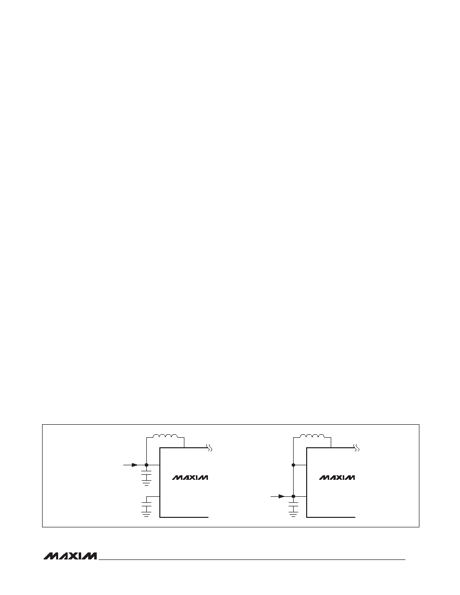
Figure 5 shows possible supply connection configura-
tions for the devices. The VCC pin should be bypassed
to GND with a minimum 1FF ceramic capacitor.
Startup
At startup, the devices perform an LED check by pull-
ing up each FB_ pin with a current source to determine
whether a string of LEDs are connected. If an FB_ pin
is not connected with LEDs, it is disabled. The process
takes approximately 1ms. Then the current sources are
turned on.
Shutdown
The devices can be placed into shutdown by pulling the
EN pin low; when in shutdown mode, the current con-
sumption is 5FA max. In the devices, the VCC voltage
drops to 0V with EN low.
Overvoltage Protection
To protect the step-up regulator when the load is open,
or the output voltage becomes excessive for any rea-
son, the devices feature a dedicated overvoltage feed-
back input by monitoring output (OVP). There are two
thresholds for OVP and they provide careful protections.
When the OVP voltage exceeds the 43V (typ) for the
MAX17129 or 25.4V for the MAX17149, an overvoltage
flag is set to enable the open-string detection. When
the OVP voltage exceeds 45.2V (typ), the internal power
MOSFET stops switching. This step-up regulator switch
is reenabled after the VOVP drops 1.8V (typ hysteresis)
below the protection threshold. This overvoltage protec-
tion feature ensures the step-up regulator fail-safe opera-
tion when the LED strings are disconnected from the
output. Considering overvoltage threshold and minimum
output regulation voltage, the MAX17149 is suitable for
3–6 LEDs per string and the MAX17129 is suitable for
6–11 LEDs per string.
Overcurrent Protection
When in overcurrent condition, the devices latch off after
a fault timer expires. If running at full brightness, the
timeout is approximately 0.8ms (typ). If dimming, this
timeout is dependent on the dimming frequency and
duty cycle: the sum of the on-time cycles, during which
the device is in overcurrent condition, must be 0.8ms
(typ) for the timeout to expire.
LED Current Sources
Maintaining uniform LED brightness and dimming capa-
bility is critical for backlight applications. The ICs are
equipped with a bank of six matched current sources.
These specialized current sources are accurate within
Q
3% and match with each other within 2%. The LED
full-scale current is set through the ISET pin (10mA <
ILED_FS < 45mA).
The minimum voltage drop across each current source
is 275mV (typ) when the LED current is 20mA. The low-
voltage drop helps reduce dissipation while maintaining
sufficient compliance to control the LED current within
the required tolerances.
The LED current sources can be disabled by connecting
the respective FB_ pin to GND before startup. When the
devices are enabled, the controller scans settings for
all FB_ pins. If a FB_ pin is not tied to GND, an internal
circuit pulls this pin high, and the controller enables the
corresponding current source to regulate the string cur-
rent. If the FB_ pin is tied to GND, the controller disables
the corresponding current regulator. The current regula-
tor cannot be disabled by connecting the respective FB_
pin to GND after the IC is enabled.
All FB_ pins in use are combined to extract a lowest FB_
voltage (LVC) (see Figure 2). LVC is fed into the step-up
regulator’s error amplifier and is used to set the output
voltage.
Figure 5. Supply Configurations for the MAX17129/MAX17149
LX
IN
VCC
VIN
6V TO 26V
MAX17129
MAX17149
LX
IN
VCC
VS
3.0V TO 5.5V
MAX17129
MAX17149
相關(guān)PDF資料 |
PDF描述 |
|---|---|
| DS1245AB-100 | 128K X 8 NON-VOLATILE SRAM MODULE, 100 ns, DMA32 |
| DS1245Y-120 | 128K X 8 NON-VOLATILE SRAM MODULE, 120 ns, DMA32 |
| DS1245AB-85 | 128K X 8 NON-VOLATILE SRAM MODULE, 85 ns, DMA32 |
| DS1245Y-85 | 128K X 8 NON-VOLATILE SRAM MODULE, 85 ns, DMA32 |
| DS1245Y-70 | 128K X 8 NON-VOLATILE SRAM MODULE, 70 ns, DMA32 |
相關(guān)代理商/技術(shù)參數(shù) |
參數(shù)描述 |
|---|---|
| DS1244Y120 | 制造商:Maxim Integrated Products 功能描述: |
| DS1244Y-120 | 制造商:Maxim Integrated Products 功能描述: |
| DS1244Y-150 | 制造商:Rochester Electronics LLC 功能描述: 制造商:Maxim Integrated Products 功能描述: |
| DS1244Y-200 | 制造商:DALLAS 制造商全稱:Dallas Semiconductor 功能描述:256K NV SRAM with Phantom Clock |
| DS1244Y-70 | 功能描述:實時時鐘 RoHS:否 制造商:Microchip Technology 功能:Clock, Calendar. Alarm RTC 總線接口:I2C 日期格式:DW:DM:M:Y 時間格式:HH:MM:SS RTC 存儲容量:64 B 電源電壓-最大:5.5 V 電源電壓-最小:1.8 V 最大工作溫度:+ 85 C 最小工作溫度: 安裝風(fēng)格:Through Hole 封裝 / 箱體:PDIP-8 封裝:Tube |
發(fā)布緊急采購,3分鐘左右您將得到回復(fù)。