- 您現(xiàn)在的位置:買賣IC網(wǎng) > PDF目錄379714 > C10423 (Hamamatsu Photonics) DRIVING CIRCUIT PDF資料下載
參數(shù)資料
| 型號: | C10423 |
| 廠商: | Hamamatsu Photonics |
| 英文描述: | DRIVING CIRCUIT |
| 中文描述: | 驅(qū)動電路 |
| 文件頁數(shù): | 2/2頁 |
| 文件大小: | 162K |
| 代理商: | C10423 |
TPT 1023E01
JUN. 2007. IP
UV TRON
DRIVING CIRCUIT C10423
HAMAMATSU PHOTONICS K.K., Electron Tube Division
314-5, Shimokanzo, Iwata City, Shizuoka Pref., 438-0193, Japan, Telephone: (81)539/62-5248, Fax: (81)539/62-2205
U.S.A.:Hamamatsu Corporation: 360 Foothill Road, P. O. Box 6910, Bridgewater. N.J. 08807-0910, U.S.A., Telephone: (1)908-231-0960, Fax: (1)908-231-1218 E-mail: usa@hamamatsu.com
Germany:Hamamatsu Photonics Deutschland GmbH: Arzbergerstr. 10, D-82211 Herrsching am Ammersee, Germany, Telephone: (49)8152-375-0, Fax: (49)8152-2658 E-mail: info@hamamatsu.de
France:Hamamatsu Photonics France S.A.R.L.: 19, Rue du Saule Trapu, Parc du Moulin de Massy, 91882 Massy Cedex, France, Telephone: (33)1 69 53 71 00, Fax: (33)1 69 53 71 10 E-mail: infos@hamamatsu.fr
United Kingdom:Hamamatsu Photonics UK Limited: 2 Howard Court, 10 Tewin Road Welwyn Garden City Hertfordshire AL7 1BW, United Kingdom, Telephone: 44-(0)1707-294888, Fax: 44(0)1707-325777 E-mail: info@hamamatsu.co.uk
North Europe:Hamamatsu Photonics Norden AB: Smidesv
gen 12, SE-171-41 SOLNA, Sweden, Telephone: (46)8-509-031-00, Fax: (46)8-509-031-01 E-mail: info@hamamatsu.se
Italy:Hamamatsu Photonics Italia: S.R.L.: Strada della Moia, 1/E, 20020 Arese, (Milano), Italy, Telephone: (39)02-935 81 733, Fax: (39)02-935 81 741 E-mail: info@hamamatsu.it
WEB SITE www.hamamatsu.com
TPT C0019EA
TPT C0020EA
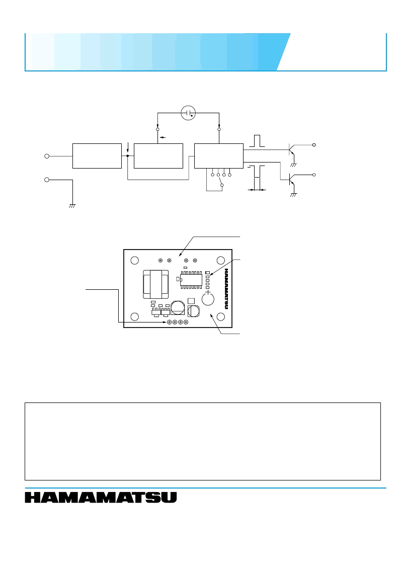
Figure 1: Schematic Diagram
Figure 2: Method of Connection
PRECAUTIONS FOR USE
G
Since the operation impedance is extremely high, the UV TRON should be connected as close as possible to the circuit
board within 5 cm.
G
Take care to avoid external noise since a C-MOS IC is used in the circuit. It is recommended that the whole PC board be put
in the shield box when it is used.
G
The DC-DC converter type high-voltage supply for this unit has a very high impedance. If the ambient humidity is high, then
electrical leakage on the printed circuit board surface might lead to a drop in the supply voltage to the UV TRON. This
voltage drop might cause lower sensitivity or malfunctions. If using the unit in a high humid environment apply a silicon-
based moisture-proof coating to the UV TRON connection terminals.
UV TRON R9454
(SOLD SEPARATELY)
K
A
CATHODE
ANODE
POWER SUPPLY
+
–
GND
CONSTANT
VOLTAGE
CIRCUIT
HIGH VOLTAGE
DC-DC
CONVERTER
SIGNAL
PROCESSING
CIRCUIT
1
3
J1
J2
10 ms
5
GND
GND
5 V
5 V
Q
Q
OUTPUT SIGNAL
WAVEFORM
OPEN COLLECTOR
OUTPUT (2)
LOW IMPEDANCE
5
9
+400 V
Tr: 50 V
80 mA
+5 V
OPEN COLLECTOR
OUTPUT (1)
HIGH IMPEDANCE
CHIP JUMPER FOR
SETTING BACKGROUND
CANCEL LEVEL
J3
J4
C
CX
J1
J2
J3
J4
2 1
G
G
A
K
+
–
7
The background cancel circuit of the C10423 is de-
signed to output a signal only when 1 to 9 or more sig-
nal pulses from the UV TRON are detected consecu-
tively within 2 seconds. The background cancel level
is set to chip jumper position 3(J2) before shipment.
If the C10423 is used in locations where a high
amount of natural excitation (background) light is
present, then change the cancel level by reconnect-
ing the jumper position to 5(J3) and 9(J4).
POWER SUPPLY INPUT
AND SIGNAL OUTPUT POINT
–
: GND
+: POWER SUPPLY (DC) 12 V to 24 V
1: OPEN COLLECTOR OUTPUT
4
HIGH IMPEDANCE
2: OPEN COLLECTOR OUTPUT
LOW IMPEDANCE
CONNECTING POINT OF UV TRON
A: Connecting Anode of UV TRON
K: Connecting Cathode of UV TRON
CHIP JUMPERS FOR SETTING
BACKGROUND CANCEL LEVEL
CX: POINT FOR ADDING A CAPACITOR TO
EXTEND OUTPUT PULSE WIDTH
5
4
The maximum rating of the open-collector transistor is 50 V / 100 mA. When connecting a relay or buzzer, use caution
not to exceed this rating.
5
The C10423 output pulse width is set to 10 ms before shipment. To expand the pulse width, connect a capacitor to this
terminal. (Make sure the polarity is correct when using an electrolytic capacitor.)
Example: CX = 1
μ
F, Pulse width = approx. 1 s
CX = 10
μ
F, Pulse width = approx. 10 s
NOTE:
相關(guān)PDF資料 |
PDF描述 |
|---|---|
| C106A | SCRs 4 AMPERES RMS 50 thru 600 VOLTS |
| C106F | SCRs 4 AMPERES RMS 50 thru 600 VOLTS |
| C106D1 | Sensitive Gate Silicon Controlled Rectifier Reverse Blocking Thyristor(4A(均方根值),400V敏感門硅控整流器反向截止晶閘管) |
| C106 | Sensitive Gate Silicon Controlled Rectifiers |
| C106B | Sensitive Gate Silicon Controlled Rectifiers |
相關(guān)代理商/技術(shù)參數(shù) |
參數(shù)描述 |
|---|---|
| C10427_CUTE-3-M | 功能描述:LED 照明鏡頭 CREE XR 3-IN-1 LENS 3 UP RoHS:否 制造商:Ledil 類型:Lenses 用于:Osram Oslon SSL 直徑:9.9 mm 顯示角:36 deg 封裝:Bulk |
| C10428_CUTE-3-SS | 功能描述:LED 照明鏡頭 CREE XR 3-IN-1 LENS 3 UP RoHS:否 制造商:Ledil 類型:Lenses 用于:Osram Oslon SSL 直徑:9.9 mm 顯示角:36 deg 封裝:Bulk |
| C10429_CUTE-3-W | 功能描述:LED 照明鏡頭 CREE XR 3-IN-1 LENS 3 UP RoHS:否 制造商:Ledil 類型:Lenses 用于:Osram Oslon SSL 直徑:9.9 mm 顯示角:36 deg 封裝:Bulk |
| C10436_MX6-3-M | 制造商:LEDIL 功能描述:50mm Triple LED Optic, Medium Beam |
| C10436_NIS83-3-M | 制造商:LEDIL 功能描述:LITEON P00 1W,3IN1 LENS,50,3 UP - Rail/Tube |
發(fā)布緊急采購,3分鐘左右您將得到回復(fù)。