- 您現(xiàn)在的位置:買賣IC網(wǎng) > PDF目錄1905 > ATF1508RE-7AU100 (Atmel)IC CPLD EE 128MC 5NS 100-TQFP PDF資料下載
參數(shù)資料
| 型號: | ATF1508RE-7AU100 |
| 廠商: | Atmel |
| 文件頁數(shù): | 18/54頁 |
| 文件大小: | 0K |
| 描述: | IC CPLD EE 128MC 5NS 100-TQFP |
| 標準包裝: | 90 |
| 系列: | ATF15xx |
| 可編程類型: | 系統(tǒng)內可編程(最少 10,000 次編程/擦除循環(huán)) |
| 最大延遲時間 tpd(1): | 7.5ns |
| 電壓電源 - 內部: | 3 V ~ 3.6 V |
| 宏單元數(shù): | 128 |
| 輸入/輸出數(shù): | 80 |
| 工作溫度: | -40°C ~ 85°C |
| 安裝類型: | 表面貼裝 |
| 封裝/外殼: | 100-TQFP |
| 供應商設備封裝: | 100-TQFP(14x14) |
| 包裝: | 托盤 |
| 產品目錄頁面: | 608 (CN2011-ZH PDF) |
第1頁第2頁第3頁第4頁第5頁第6頁第7頁第8頁第9頁第10頁第11頁第12頁第13頁第14頁第15頁第16頁第17頁當前第18頁第19頁第20頁第21頁第22頁第23頁第24頁第25頁第26頁第27頁第28頁第29頁第30頁第31頁第32頁第33頁第34頁第35頁第36頁第37頁第38頁第39頁第40頁第41頁第42頁第43頁第44頁第45頁第46頁第47頁第48頁第49頁第50頁第51頁第52頁第53頁第54頁
Atmel-ISP Hardware
4-2
Atmel ATF15xx Family: ISP Devices User Guide
A switch block (SW2) containing four DIP switches is located on the top of the ISP
board. It is used as a socket selector. If you are programming using an 84PLCC
socket, DIP Switch 4 from this group must be in the OFF (down) position. If you
are using a daughter board, DIP Switch 4 from SW2 must be in the ON (up) position.
The requirement holds whether you are using either the Atmel-ISP cable or Byte-
Blaster/ByteBlasterMV cable.
Special features have been added to the ISP board (Rev. 3 or later) to support multi-
voltage (3V/5V) device programming. These include a power supply regulation circuit
that can supply either 3V or 5V supply voltage (V
CC) and a 3/5V header to change the
V
CC voltage value. Additional changes to the board include: a better power-on/off switch,
improved PC board layout of regulator near the 84-pin PLCC socket, battery connector
terminals that are directly soldered on the board and other changes.
To select the proper V
CC voltage, use jumper JP3 on the Atmel-ISP board (Rev. 3 and
later). If the left two jumpers are connected, V
CC will be set to 5V. If the right two jumpers
are connected, V
CC will be 3.3V.
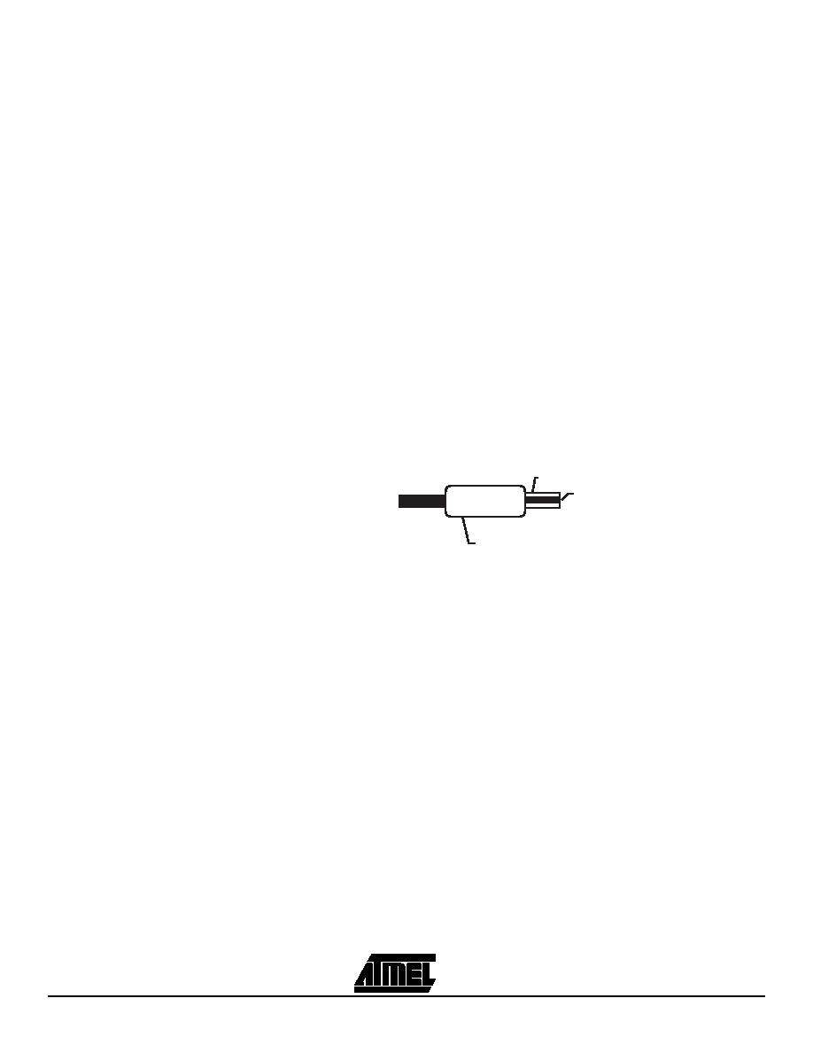
Power to the Atmel-ISP board is supplied by either an Atmel 9V AC/DC adapter or a 9V
battery. Use the Atmel AC/DC adapter to power the board as some adapters may have
the power and ground connections reversed, which can damage the ISP board. If you
are using a different AC/DC adapter, make sure that the center pin of the socket
adapter is at 9V, as shown in Figure 4-1.
Figure 4-1. DC Adapter Socket
You can find the revision of the Atmel-ISP board by looking on the front of it just below
the prototype area and above the Q2 and Q3 labels. It is always recommended that you
use the latest revision of the Atmel-ISP board when programming Atmel devices.
If you are unsure which is the latest ISP board revision, contact Atmel PLD Applications.
4.1.1
Optional Features
on Atmel-ISP
Board Useful for
Prototyping
These features are not included in the Atmel-ISP board. The following components can
be soldered onto the ISP board in order to test functionality of specific Atmel ISP
devices.
LEDs: LED1 is used for the power supply and the other two (LED2 and LED3) are for
prototyping.
Crystal oscillator, 1 MHz (Y1)
Two momentary input switches (PBSW1 and PBSW2)
4-position slide switch that encodes to two inputs (SW1)
5 alphanumeric LED displays with drivers (DSP1 - 5)
A user prototyping area
One 84-pin PLCC programming socket
One 10-pin JTAG header
Signal breakout headers
+9V
GND
DC Adapter
Connector
相關PDF資料 |
PDF描述 |
|---|---|
| ATF16LV8C-10SI | IC PLD EE 8CELL 3V LP 20-SOIC |
| ATF16V8BQL-15XC | IC PLD 15NS 20TSSOP |
| ATF16V8C-7XU | IC PLD 7NS 20TSSOP |
| ATF16V8CZ-15XC | IC PLD 15NS 20TSSOP |
| ATF20V8BQL-15PU | IC PLD 15NS 24DIP |
相關代理商/技術參數(shù) |
參數(shù)描述 |
|---|---|
| ATF1508RE-7CU132 | 制造商:ATMEL 制造商全稱:ATMEL Corporation 功能描述:Highperformance CPLD |
| ATF1508SE | 制造商:ATMEL 制造商全稱:ATMEL Corporation 功能描述:Family Datasheet |
| ATF1508SE(L) | 制造商:未知廠家 制造商全稱:未知廠家 功能描述:ATF1502/04/08/16SE(L) Preliminary [Updated 9/02. 69 Pages] Second Generation Industry Compatible 5V Logic Doubling CPLDs 32-512 Macrocells. standard & low power w/ISP |
| ATF1508SL | 制造商:ATMEL 制造商全稱:ATMEL Corporation 功能描述:Family Datasheet |
| ATF1508Z | 制造商:未知廠家 制造商全稱:未知廠家 功能描述:High Performance E2PLD |
發(fā)布緊急采購,3分鐘左右您將得到回復。