- 您現(xiàn)在的位置:買(mǎi)賣(mài)IC網(wǎng) > PDF目錄379669 > AN231E04 (Electronic Theatre Controls, Inc.) Dynamically Reconfigurable dpASP PDF資料下載
參數(shù)資料
| 型號(hào): | AN231E04 |
| 廠商: | Electronic Theatre Controls, Inc. |
| 英文描述: | Dynamically Reconfigurable dpASP |
| 中文描述: | 動(dòng)態(tài)可重構(gòu)dpASP |
| 文件頁(yè)數(shù): | 9/24頁(yè) |
| 文件大?。?/td> | 445K |
| 代理商: | AN231E04 |
第1頁(yè)第2頁(yè)第3頁(yè)第4頁(yè)第5頁(yè)第6頁(yè)第7頁(yè)第8頁(yè)當(dāng)前第9頁(yè)第10頁(yè)第11頁(yè)第12頁(yè)第13頁(yè)第14頁(yè)第15頁(yè)第16頁(yè)第17頁(yè)第18頁(yè)第19頁(yè)第20頁(yè)第21頁(yè)第22頁(yè)第23頁(yè)第24頁(yè)
AN231E04 Datasheet – Dynamically Reconfigurable dpASP
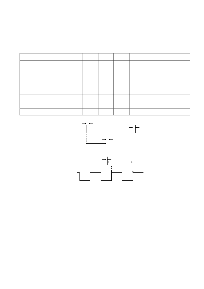
RAM Transfer – Trigger and Arm
These digital inputs do not have dedicated pins, a connection exists within the dpASP, an external signal can be routed to
either of these virtual pins from a type2 I/O cell (I/O cells 5, 6 and 7. Pins 15,16,17,18,19 or 20).
The purpose of these virtual pins is to extend optional asynchronous timing control of the dpASP configuration to the user.
DS231000-U001d
- 9 -
1.4.8
Parameter
Input Voltage Low
Input Voltage High
Minimum pulse width
connected to where
Pulse-Pulse edge delay
Symbol
Vil
Vih
T
PW
setup time
Min
0
70
Typ
Max
30
100
Unit
%
%
Comment
% of DVDD
% of DVDD
Time to register the event
internally.
Delay between pre-trigger and
trigger. Need not be observed if
pre-trigger is not used, is set at
the end of configuration
automatically.
Delay from trigger rising edge to
internal execute event.
Duration of execute pulse
guaranteed 1 ACLK period. Can
be as long as 2 periods
depending on relative phases.
Pre-trigger circuit is reset ready to
accept another pre-trigger.
5
-
-
ns
T
PT-T
setup time
10
-
-
ns
Execute delay
T
EXDLY
0
10
20
ns
Execute minimum width
T
MinEW
1 ALCK
-
2 ACLK
-
Pre-trigger reset.
T
PTR
10
-
-
ns
Pre-trigger
Trigger
ACLK
T
PW
T
PW
T
PT-T
T
MinEW
T
EXDLY
Internal
RAM
execute
T
PTR
edge (n)
edge (n+1)
AnadigmDesigner2 options, (these are set using the software tool AnadigmDesigner2)
RAM Transfer Trigger = Automatic
:
RAM transfer happens automatically immediately after the “end” byte of a configuration bit stream. Timing control is entirely inside the
AN231E04 device and not visible to a user.
RAM Transfer Trigger = Event driven
.
RAM Trigger = Off
.
no pre-trigger used. The “end” byte of configuration bit stream arms the RAM transfer and the user signal then acts
as the trigger.
Arm Trigger = On
External Signal Allowed = Trigger
. This setting allows the external signal connected to be the trigger,
Arming must be from an internal signal.
External Signal Allowed = Arm
. This setting allows the external signal connected to be the arming signal,
Trigger be from an internal signal.
RAM Transfer Trigger = Clock synch
RAM transfer happens automatically immediately following the first occurrence of all internal clocks being scyncronous. Timing control is
entirely inside the AN231E04 device and not visible to a user.
HINT: The RAM transfer timings above are for the trigger block hardware - The
Trigger
and
Arm
signals can come from many
sources, propagation delays to the trigger block inputs will vary depending on the source and routing of the signals to this block.
相關(guān)PDF資料 |
PDF描述 |
|---|---|
| AN231E04-E2-QFNSP | Dynamically Reconfigurable dpASP |
| AN231E04-E2-QFNTR | Dynamically Reconfigurable dpASP |
| AN231E04-E2-QFNTY | Dynamically Reconfigurable dpASP |
| AN231K04-DVLP3 | Dynamically Reconfigurable dpASP |
| AN321 | AND / NOR circuit providing the logical function |
相關(guān)代理商/技術(shù)參數(shù) |
參數(shù)描述 |
|---|---|
| AN231E04-E2-QFNSP | 制造商:未知廠家 制造商全稱(chēng):未知廠家 功能描述:Dynamically Reconfigurable dpASP |
| AN231E04-E2-QFNTR | 制造商:未知廠家 制造商全稱(chēng):未知廠家 功能描述:Dynamically Reconfigurable dpASP |
| AN231E04-E2-QFNTY | 制造商:Anadigm 功能描述:Analog Signal Processor 44-Pin QFN EP Tray |
| AN231K04-DVLP3 | 制造商:未知廠家 制造商全稱(chēng):未知廠家 功能描述:Dynamically Reconfigurable dpASP |
| AN232 | 制造商:MICROCHIP 制造商全稱(chēng):Microchip Technology 功能描述:Low Frequency Magnetic Transmitter Design |
發(fā)布緊急采購(gòu),3分鐘左右您將得到回復(fù)。