- 您現(xiàn)在的位置:買賣IC網(wǎng) > PDF目錄223321 > AEE00C24 1-OUTPUT 10 W DC-DC REG PWR SUPPLY MODULE PDF資料下載
參數(shù)資料
| 型號: | AEE00C24 |
| 元件分類: | 電源模塊 |
| 英文描述: | 1-OUTPUT 10 W DC-DC REG PWR SUPPLY MODULE |
| 封裝: | 2 X 1 INCH, MODULE-4 |
| 文件頁數(shù): | 13/22頁 |
| 文件大?。?/td> | 301K |
| 代理商: | AEE00C24 |
A
A
A E
E
E E
E
E 0
0
0 1
1
1 L
L
L 2
2
2 4
4
4 ////L
L
L 4
4
4 8
8
8 D
D
D C
C
C --D
D
D C
C
C C
C
C o
o
o n
n
n v
v
v e
e
e rrrrtttte
e
e rrrrs
s
1
1 8
8
8 --3
3
3 6
6
6 V
V
V d
d
d c
c
c a
a
a n
n
n d
d
d 3
3
3 6
6
6 --7
7
7 2
2
2 V
V
V d
d
d c
c
c IIIIn
n
n p
p
p u
u
u tttt,,,, 1
1
1 0
0
0 W
W
Wa
a
a tttttttt S
S
S iiiin
n
n g
g
g lllle
e
e O
O
O u
u
u ttttp
p
p u
u
u tttt
-20-
Redundant Operation
A common requirement in high reliability sys-
tems is to provide redundant power supplies.
The easiest way to do this is to place two con-
verters in parallel, providing fault tolerance but
not load sharing. Oring diodes should be used
to ensure that failure of one converter will not
cause failure of the second. Figure 13 shows
such an arrangement. Upon application of
power, one of the converters will provide a
slightly higher output voltage and will support
the full load demand. The second converter will
see a zero load condition and will “idle”. If the
first converter should fail, the second converter
will support the full load. When designing
redundant converter circuits, Shottky diodes
should be used to minimize the forward voltage
drop. The voltage drop across the Shottky
diodes must also be considered when deter-
mining load voltage requirements.
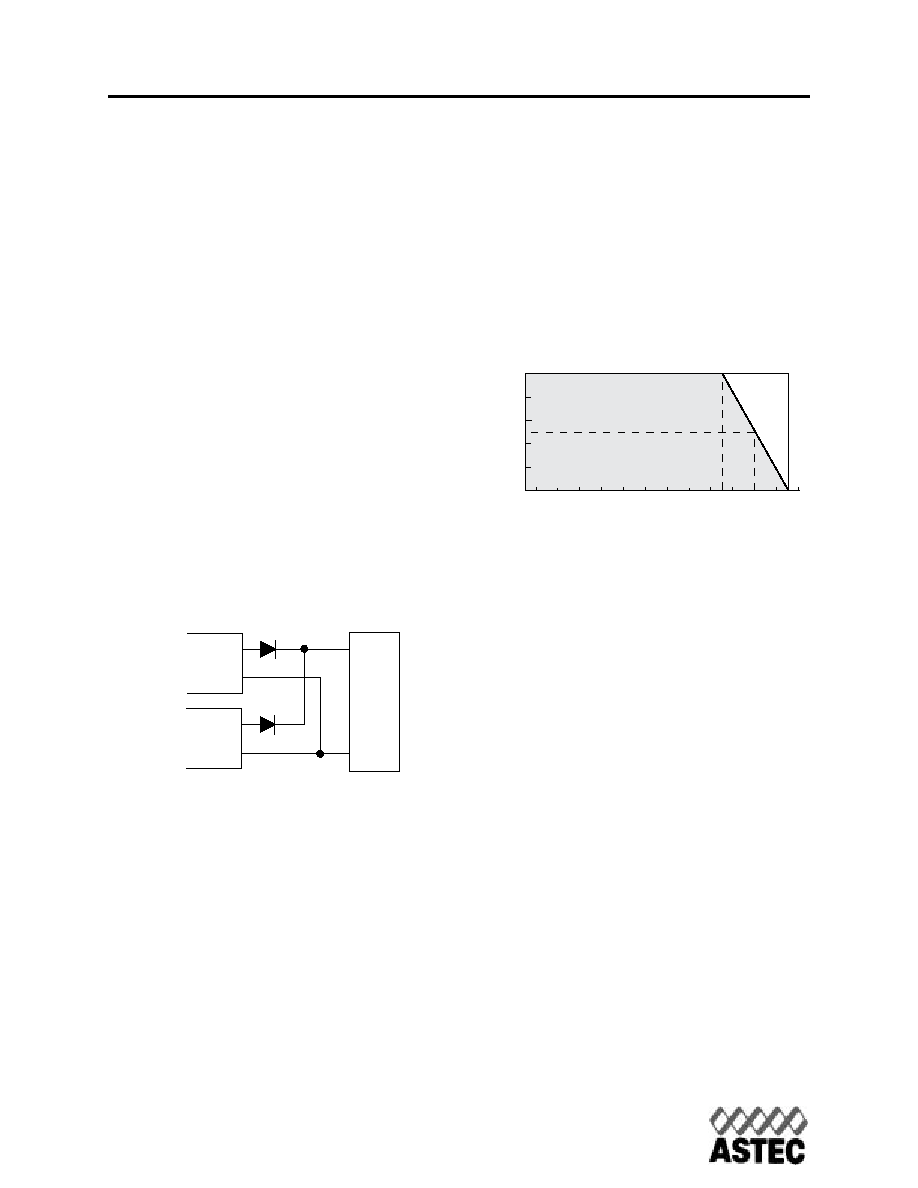
Module Derating
Thermal Derating
AEE single and dual output converters are
rated for full power up to a case temperature
of 95°C. Under typical conditions this equates
to an ambient temperature of 65°C. For opera-
tion above ambient air temperatures of 65°C,
output power must be derated as shown in
Figure 14, or airflow over the converter must
be provided. When airflow is provided, the
case temperature of the converter should be
used to determine maximum temperature lim-
its. The minimum operating temperature for
the AEE is -25°C. Operation at temperatures
as low as -40°C is possible, but output perfor-
mance below -25°C is not specified.
Mechanical
Considerations
Installation
Although AEE series converters can be mount-
ed in any orientation, free air-flowing must be
taken. Normally power components are always
put at the end of the airflow path or have the
separate airflow paths. This can keep other
system equipment cooler and increase compo-
nent life spans.
Soldering
AEE series converters are compatible with
standard wave soldering techniques. When
wave soldering, the converter pins should be
preheated for 20-30 seconds at 110° C, and
wave soldered at 260°C for less than 10 sec-
onds.
When hand soldering, the iron temperature
+Vout
-Vout
+Vout
-Vout
Load
Fig.13 Redundant Operation
0
20
40
60
80
100
70
60
50
40
30
20
10
0
-10
-20
Ambient Temperature in degrees C
P
ercent
maxim
um
output
po
w
e
r
Safe Operating Area
80
90
Maxim
um
Case
T
emper
ature
100
Fig.14 Derating Curves
www.astec.com
USA
Europe
Asia
TEL: 1-760-930-4600
44-(0)1384-842-211
852-2437-9662
FAX: 1-760-930-0698
44-(0)1384-843-355
852-2402-4426
相關(guān)PDF資料 |
PDF描述 |
|---|---|
| AEE01B36-L | 1-OUTPUT 15 W DC-DC REG PWR SUPPLY MODULE |
| AFBR-2010S | FIBER OPTIC RECEIVER, 630-685nm, 50Mbps, THROUGH HOLE MOUNT |
| AFBR-2010 | FIBER OPTIC RECEIVER, 630-685nm, 50Mbps, THROUGH HOLE MOUNT |
| AFBR-57D7APZ | FIBER OPTIC TRANSCEIVER, 840-860nm, 8500Mbps(Tx), 8500Mbps(Rx), SURFACE MOUNT, LC CONNECTOR |
| AFBR-57J5APZ | FIBER OPTIC TRANSCEIVER, 830-860nm, 24576Mbps(Tx), 24576Mbps(Rx), BOARD/PANEL MOUNT, LC CONNECTOR |
相關(guān)代理商/技術(shù)參數(shù) |
參數(shù)描述 |
|---|---|
| AEE00C24L | 制造商:Johnson Components 功能描述:24V-15V 10W 1 X 2 X 0.35 H |
| AEE00C48 | 功能描述:DC/DC轉(zhuǎn)換器 CONV DC-DC 10W 24VIN RoHS:否 制造商:Murata 產(chǎn)品: 輸出功率: 輸入電壓范圍:3.6 V to 5.5 V 輸入電壓(標(biāo)稱): 輸出端數(shù)量:1 輸出電壓(通道 1):3.3 V 輸出電流(通道 1):600 mA 輸出電壓(通道 2): 輸出電流(通道 2): 安裝風(fēng)格:SMD/SMT 封裝 / 箱體尺寸: |
| AEE00C48-L | 制造商:Emerson Network Power - Embedded Power 功能描述:- Trays |
| AEE00CC12 | 制造商:未知廠家 制造商全稱:未知廠家 功能描述:DC to DC Converter |
| AEE00CC12-1 | 制造商:未知廠家 制造商全稱:未知廠家 功能描述:DC to DC Converter |
發(fā)布緊急采購,3分鐘左右您將得到回復(fù)。