- 您現(xiàn)在的位置:買賣IC網(wǎng) > PDF目錄223321 > AEE00C24 1-OUTPUT 10 W DC-DC REG PWR SUPPLY MODULE PDF資料下載
參數(shù)資料
| 型號: | AEE00C24 |
| 元件分類: | 電源模塊 |
| 英文描述: | 1-OUTPUT 10 W DC-DC REG PWR SUPPLY MODULE |
| 封裝: | 2 X 1 INCH, MODULE-4 |
| 文件頁數(shù): | 11/22頁 |
| 文件大小: | 301K |
| 代理商: | AEE00C24 |

A
A
A E
E
E E
E
E 0
0
0 1
1
1 L
L
L 2
2
2 4
4
4 ////L
L
L 4
4
4 8
8
8 D
D
D C
C
C --D
D
D C
C
C C
C
C o
o
o n
n
n v
v
v e
e
e rrrrtttte
e
e rrrrs
s
1
1 8
8
8 --3
3
3 6
6
6 V
V
V d
d
d c
c
c a
a
a n
n
n d
d
d 3
3
3 6
6
6 --7
7
7 2
2
2 V
V
V d
d
d c
c
c IIIIn
n
n p
p
p u
u
u tttt,,,, 1
1
1 0
0
0 W
W
Wa
a
a tttttttt S
S
S iiiin
n
n g
g
g lllle
e
e O
O
O u
u
u ttttp
p
p u
u
u tttt
-19-
Design Considerations
Ground Loops
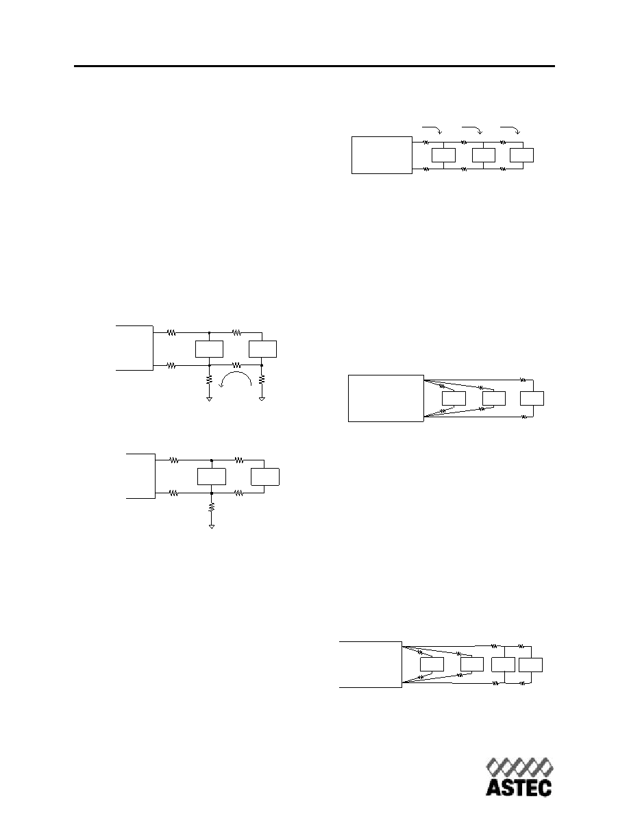
Ground loops occur when different circuits are
given multiple paths to common or earth
ground, as shown in Figure 8. Multiple ground
points can slightly different potential and cause
current flow through the circuit from one point to
another. This can result in additional noise in all
the circuits. To eliminate the problem, circuits
should be designed with a single ground con-
nection as shown in Figure 9.
Parallel Power Distribution
Figure 10 shows a typical parallel power distri-
bution design. Such designs, sometimes called
daisy chains, can be used for very low output
currents, but are not normally recommended.
The voltage across loads far from the source
can vary greatly depending on the IR drops
along the leads and changes in the loads clos-
er to the source. Dynamic load conditions
increase the potential problems.
Radial Power Distribution
Radial power distribution is the preferred
method of providing power to the load. Figure
11 shows how individual loads are connected
directly to the power source. This arrangement
requires additional power leads, but it avoids
the voltage variation problems associated with
the parallel power distribution technique.
Mixed Distribution
In the real world a combination of parallel and
radial power distribution is often used. Dynamic
and high current loads are connected using a
radial design, while static and low current loads
can be connected in parallel. This combined
approach minimizes the drawbacks of a parallel
design when a purely radial design is not feasi-
ble.
+Vout
-Vout
Load
RLine
Ground
Loop
Fig.8. Ground Loops
Fig.9 Single Point Ground
+Vout
-Vout
Load
RLine
Load 1
Load 2
Load 3
+Vout
-Vout
RL1
RL2
RL3
RG1
RG2
RG3
I1 + I2 + I3
I2 + I3
I3
RL = Lead Resistance
RG = Ground Lead Resistance
Fig.10 Parallel Power Distribution
Load 1
Load 2
Load 3
+Vout
-Vout
RL1
RL2
RL3
RG1
RG2
RG3
RL = Lead Resistance
RG = Ground Lead Resistance
Fig.11 Radial Power Distribution
Load 1
Load 2
Load 3
+Vout
-Vout
RL1
RL2
RL3
RG1
RG2
RG3
RL = Lead Resistance
RG = Ground Lead Resistance
Load 4
RL4
RG4
Fig.12 Mixed Power Distribution
www.astec.com
USA
Europe
Asia
TEL: 1-760-930-4600
44-(0)1384-842-211
852-2437-9662
FAX: 1-760-930-0698
44-(0)1384-843-355
852-2402-4426
相關(guān)PDF資料 |
PDF描述 |
|---|---|
| AEE01B36-L | 1-OUTPUT 15 W DC-DC REG PWR SUPPLY MODULE |
| AFBR-2010S | FIBER OPTIC RECEIVER, 630-685nm, 50Mbps, THROUGH HOLE MOUNT |
| AFBR-2010 | FIBER OPTIC RECEIVER, 630-685nm, 50Mbps, THROUGH HOLE MOUNT |
| AFBR-57D7APZ | FIBER OPTIC TRANSCEIVER, 840-860nm, 8500Mbps(Tx), 8500Mbps(Rx), SURFACE MOUNT, LC CONNECTOR |
| AFBR-57J5APZ | FIBER OPTIC TRANSCEIVER, 830-860nm, 24576Mbps(Tx), 24576Mbps(Rx), BOARD/PANEL MOUNT, LC CONNECTOR |
相關(guān)代理商/技術(shù)參數(shù) |
參數(shù)描述 |
|---|---|
| AEE00C24L | 制造商:Johnson Components 功能描述:24V-15V 10W 1 X 2 X 0.35 H |
| AEE00C48 | 功能描述:DC/DC轉(zhuǎn)換器 CONV DC-DC 10W 24VIN RoHS:否 制造商:Murata 產(chǎn)品: 輸出功率: 輸入電壓范圍:3.6 V to 5.5 V 輸入電壓(標(biāo)稱): 輸出端數(shù)量:1 輸出電壓(通道 1):3.3 V 輸出電流(通道 1):600 mA 輸出電壓(通道 2): 輸出電流(通道 2): 安裝風(fēng)格:SMD/SMT 封裝 / 箱體尺寸: |
| AEE00C48-L | 制造商:Emerson Network Power - Embedded Power 功能描述:- Trays |
| AEE00CC12 | 制造商:未知廠家 制造商全稱:未知廠家 功能描述:DC to DC Converter |
| AEE00CC12-1 | 制造商:未知廠家 制造商全稱:未知廠家 功能描述:DC to DC Converter |
發(fā)布緊急采購,3分鐘左右您將得到回復(fù)。