- 您現(xiàn)在的位置:買賣IC網(wǎng) > PDF目錄375269 > ADXL05AH (ANALOG DEVICES INC) Circular Connector; No. of Contacts:11; Series:LJTP02R; Body Material:Aluminum; Connecting Termination:Crimp; Connector Shell Size:21; Circular Contact Gender:Socket; Circular Shell Style:Box Mount Receptacle PDF資料下載
參數(shù)資料
| 型號: | ADXL05AH |
| 廠商: | ANALOG DEVICES INC |
| 元件分類: | 模擬信號調(diào)理 |
| 英文描述: | Circular Connector; No. of Contacts:11; Series:LJTP02R; Body Material:Aluminum; Connecting Termination:Crimp; Connector Shell Size:21; Circular Contact Gender:Socket; Circular Shell Style:Box Mount Receptacle |
| 中文描述: | SPECIALTY ANALOG CIRCUIT, MBCY10 |
| 封裝: | HERMETIC SEALED, METAL CAN, TO-100, 10 PIN |
| 文件頁數(shù): | 13/20頁 |
| 文件大?。?/td> | 281K |
| 代理商: | ADXL05AH |
ADXL05
–13–
REV. B
T he equivalent rms noise of the bandpass filter is equal to
500
μ
g
/
Hz
×
For example, the typical rms noise of the ADX L05 using 1 pole
ac coupling with a bandwidth of 10 Hz and 1 pole low-pass
filter of 100 Hz is:
Noise
(
rms
)
=
500
μ
g
/
Hz
×
1.5(100) ±(10/1.5)
=
5,987
μ
g rmsor
≈
5.9
mg rms
Because the ADX L05’s noise is for all practical purposes
Gaussian in amplitude distribution, the highest noise amplitudes
have the smallest (yet nonzero) probability. Peak-to-peak noise
is therefore difficult to measure and can only be estimated due
to its statistical nature. T able II is useful for estimating the
probabilities of exceeding various peak values, given the rms
value.
(1.5
F
H
) ±(
F
L
/1.5) .
T able II.
Nominal Peak-to-
Peak Value
% of T ime that Noise Will E xceed
Nominal Peak-to-Peak Value
2.0
×
rms
4.0
×
rms
6.0
×
rms
6.6
×
rms
8.0
×
rms
32%
4.6%
0.27%
0.1%
0.006%
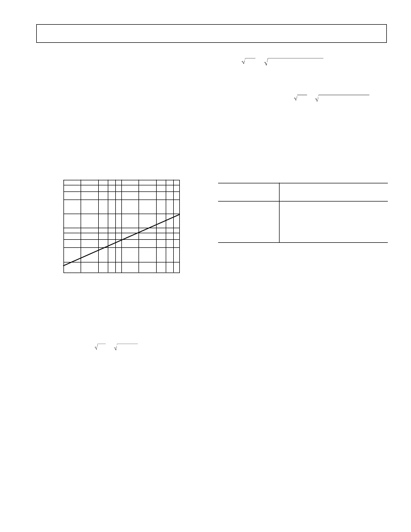
RMS and peak-to-peak noise (for 0.1% uncertainty) for various
bandwidths is estimated in Figure 24. As shown by the figure,
device noise drops dramatically as the operating bandwidth is
reduced. For example, when operated in a 1 kHz bandwidth,
the ADX L05 typically has an rms noise level of 19 mg. With
±
5
g
applied accelerations, this 19 mg resolution limit is nor-
mally quite satisfactory; but for smaller acceleration levels the
noise is now a much greater percentage of the signal. As shown
by the figure, when the device bandwidth is rolled off to 100 Hz,
the noise level is reduced to approximately 6 mg, and at 10 Hz it
is down to less than 2 mg.
Alternatively, the signal-to-noise ratio may be improved consid-
erably by using a microprocessor to perform multiple measure-
ments and then compute the average signal level. When using
this technique, with 100 measurements, the signal-to-noise ratio
will be increased by a factor of 10 (20 dB).
DE VICE BANDWIDT H VS. ME ASURE ME NT
RE SOLUT ION
Although an accelerometer is usually specified according to its
full scale (clipping)
g
level, the limiting resolution of the device,
i.e., its minimum discernible input level, is extremely important
when measuring low
g
accelerations.
T he limiting resolution is predominantly set by the measure-
ment noise “floor” which includes the ambient background
noise and the noise of the ADX L05 itself. T he level of the noise
floor varies directly with the bandwidth of the measurement. As
the measurement bandwidth is reduced, the noise floor drops,
improving the signal-to-noise ratio of the measurement and in-
creasing its resolution.
T he bandwidth of the accelerometer can be easily reduced by
adding low-pass or bandpass filtering. Figure 24 shows the typi-
cal noise vs. bandwidth characteristic of the ADX L05.
3dB BANDWIDTH – Hz
100mg
1mg
10mg
10
1k
100
N
660mg
66mg
6.6mg
N
Figure 24. Noise Level vs. 3 dB Bandwidth
T he output noise of the ADX L05 scales with the square root of
the measurement bandwidth. With a single pole roll-off, the
equivalent rms noise bandwidth is
π
divided by 2 or approxi-
mately 1.5 times the 3 dB bandwidth. For example, the typical
rms noise of the ADX L05J using a 100 Hz one pole post filter is:
Noise
(
rms
)
=
500
μ
g
/
Hz
×
For the bandpass filter of Figure 27 where both ac coupling and
low pass filtering are used, the low frequency roll-off, F
L
, is de-
termined by C4 and R1 and the high frequency roll-off, F
H
, is
determined by the 1-pole post filter R3, C5.
100(1.5)
=
6,124
μ
g or
6.1
mg rms
相關(guān)PDF資料 |
PDF描述 |
|---|---|
| ADXL05JH | Circular Connector; No. of Contacts:79; Series:LJTP02R; Body Material:Aluminum; Connecting Termination:Crimp; Connector Shell Size:21; Circular Contact Gender:Pin; Circular Shell Style:Box Mount Receptacle; Insert Arrangement:21-35 |
| ADXL05 | Single Chip Accelerometer with Signal Conditioning(帶信號調(diào)節(jié)的單片加速計) |
| ADXL105* | High Accuracy +1 g to +5 g Single Axis iMEMS Accelerometer with Analog Input |
| ADXL105AQC | Circular Connector; No. of Contacts:128; Series:LJTP02R; Body Material:Aluminum; Connecting Termination:Crimp; Connector Shell Size:25; Circular Contact Gender:Socket; Circular Shell Style:Box Mount Receptacle |
| ADXL105JQC | High Accuracy 61 g to 65 g Single Axis iMEMS Accelerometer with Analog Input |
相關(guān)代理商/技術(shù)參數(shù) |
參數(shù)描述 |
|---|---|
| ADXL05BH | 制造商:未知廠家 制造商全稱:未知廠家 功能描述:Acceleration Detector |
| ADXL05EM-1 | 制造商:Rochester Electronics LLC 功能描述:- Bulk 制造商:Analog Devices 功能描述: |
| ADXL05JH | 制造商:AD 制造商全稱:Analog Devices 功能描述:+-1 g to +-5 g Single Chip Accelerometer with Signal Conditioning |
| ADXL05KH | 制造商:未知廠家 制造商全稱:未知廠家 功能描述:Acceleration Detector |
| ADXL05TH | 制造商:未知廠家 制造商全稱:未知廠家 功能描述:Acceleration Detector |
發(fā)布緊急采購,3分鐘左右您將得到回復(fù)。