- 您現(xiàn)在的位置:買賣IC網(wǎng) > PDF目錄373980 > ADE7754ARRL (ANALOG DEVICES INC) ADE7754 PDF資料下載
參數(shù)資料
| 型號: | ADE7754ARRL |
| 廠商: | ANALOG DEVICES INC |
| 元件分類: | 模擬信號調(diào)理 |
| 英文描述: | ADE7754 |
| 中文描述: | SPECIALTY ANALOG CIRCUIT, PDSO24 |
| 封裝: | MS-013AD, SOIC-24 |
| 文件頁數(shù): | 29/44頁 |
| 文件大?。?/td> | 630K |
| 代理商: | ADE7754ARRL |
第1頁第2頁第3頁第4頁第5頁第6頁第7頁第8頁第9頁第10頁第11頁第12頁第13頁第14頁第15頁第16頁第17頁第18頁第19頁第20頁第21頁第22頁第23頁第24頁第25頁第26頁第27頁第28頁當(dāng)前第29頁第30頁第31頁第32頁第33頁第34頁第35頁第36頁第37頁第38頁第39頁第40頁第41頁第42頁第43頁第44頁
REV. PrG 01/03
PRELIMINARY TECHNICAL DATA
ADE7754
–
29
–
Figure 36 shows this Apparent Energy accumulation for full
scale signals (sinusoidal) on the analog inputs. The three
curves displayed, illustrate the minimum time it takes the
energy register to roll-over when the individual VA Gain
registers contents are all equal to 3FFh, 000h and 800h. The
VA Gain registers are used to carry out an apparent power
calibration in the ADE7754. As shown, the fastest integration
time will occur when the VA Gain registers are set to
maximum full scale, i.e., 3FFh.
00,0000h
7F,FFFFh
80,0000h
3F,FFFFh
40,0000h
VAENERGY[23:0]
Time
(seconds)
AVAG = BVAG = CVAG = 3FFh
AVAG = BVAG = CVAG = 000h
AVAG = BVAG = CVAG = 800h
131
262
393
65.5
196.5
327.5
Figure 36 - Energy register roll-over time for full-scale
power (Minimum & Maximum Power Gain)
Note that the Apparent Energy register contents roll-over to
full-scale negative (80,0000h) and continue increasing in
value when the power or energy flow is positive - see Figure
36.
By using the Interrupt Enable register, the ADE7754 can be
configured to issue an interrupt (
IRQ
) when the Apparent
Energy register is half full (positive or negative).
Integration times under steady load
As mentioned in the last section, the discrete time sample
period (T) for the accumulation register is 1.2μs (12/
CLKIN). With full-scale sinusoidal signals on the analog
inputs and the VA Gain registers set to 000h, the average
word value from each Apparent Power stage is D1B71h - see
Apparent Power output range
. The maximum value which can be
stored in the Apparent Energy register before it over-flows is
2
23
-1
or FF,FFFFh. As the average word value is added to
the internal register which can store 2
48
- 1 or
FFFF,FFFF,FFFFh before it overflows, the integration
time under these conditions with VADIV=0 is calculated as
follows:
Time
FFFF FFFF FFFFh
1 71
×
3
h
s
s
s
=
×
=
=
,
,
.
min
1 2
131
2
11
μ
When VADIV is set to a value different from 0, the integra-
tion time varies as shown on Equation 23.
Time = Time
WDIV=0
x VADIV (23)
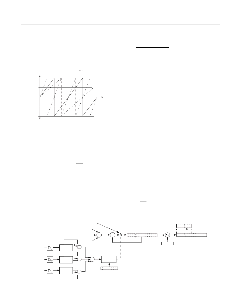
LINE APPARENT ENERGY ACCUMULATION
The ADE7754 is designed with a special Apparent Energy
accumulation mode which simplifies the calibration process.
By using the on-chip zero-crossing detection, the ADE7754
accumulates the Apparent Power signal in the LVAENERGY
register for an integral number of half cycles, as shown in
Figure 37. The line Apparent energy accumulation mode is
always active.
Each one of three phases zero-crossing detection can contrib-
ute to the accumulation of the half line cycles. Phase A, B and
C zero crossings are taken into account when counting the
number of half line cycle by setting to logic one bits 4-6 of
the MMODE register. Selecting phases for the Zero crossing
counting has also the effect of enabling the Zero-crossing
detection, Zero-crossing Time-Out and Period Measure-
ment for the corresponding phase as described in the
Zero-crossing Detection paragraph.
The number of half line cycles is specified in the LINCYC
register. LINCYC is an unsigned 16-bit register. The
ADE7754 can accumulate Apparent Power for up to 65535
combined half cycles. Because the Apparent Power is inte-
grated on the same integral number of line cycles as the Line
Active Energy register, these two values can be compared
easily - see Energy Scaling. The active and apparent Energy
are calculated more accurately because of this precise timing
control and provide all the information needed for Reactive
Power and Power Factor calculation. At the end of an energy
calibration cycle the LINCYC flag in the Interrupt Status
register is set. If the LINCYC mask bit in the Interrupt Mask
register is enabled, the
IRQ
output will also go active low.
Thus the
IRQ
line can also be used to signal the end of a
calibration.
+
+
Σ
CALIBRATION
CONTROL
LINCYC[15:0]
Σ
+
+
Apparent Power
Phase A
Apparent Power
Phase B
Apparent Power
Phase C
ACCUMULATE APPARENT POWER DURING
LINCYC ZERO-CROSSINGS
48
0
48
0
LVAENERGY[23:0]
VADIV
23
0
LPF1
FROM VA
ADC
ZEROCROSS
DETECT
LPF1
FROM VB
ADC
ZEROCROSS
DETECT
LPF1
FROM VC
ADC
ZEROCROSS
DETECT
MMODE register
bit 6
MMODE register
bit 4
MMODE register
bit 5
Figure 37 - ADE7754 Apparent Energy Calibration
相關(guān)PDF資料 |
PDF描述 |
|---|---|
| ADE7755AN-REF | Energy Metering IC with Pulse Output |
| ADE7755ARSRL | Energy Metering IC with Pulse Output |
| ADE7755 | Energy Metering IC with Pulse Output |
| ADE7755ARS | Energy Metering IC with Pulse Output |
| ADE7756EB | Evaluation Board Documentation AD7756 Energy metering IC |
相關(guān)代理商/技術(shù)參數(shù) |
參數(shù)描述 |
|---|---|
| ADE7754ARZ | 功能描述:IC ENERGY METERING 3PHASE 24SOIC RoHS:是 類別:集成電路 (IC) >> PMIC - 能量測量 系列:- 產(chǎn)品培訓(xùn)模塊:Lead (SnPb) Finish for COTS Obsolescence Mitigation Program 標(biāo)準(zhǔn)包裝:2,500 系列:* |
| ADE7754ARZRL | 功能描述:IC ENERGY METERING 3PHASE 24SOIC RoHS:是 類別:集成電路 (IC) >> PMIC - 能量測量 系列:- 產(chǎn)品培訓(xùn)模塊:Lead (SnPb) Finish for COTS Obsolescence Mitigation Program 標(biāo)準(zhǔn)包裝:2,500 系列:* |
| ADE7755 | 制造商:AD 制造商全稱:Analog Devices 功能描述:Energy Metering IC with Pulse Output |
| ADE7755AARSRL | 制造商:Analog Devices 功能描述:ENERGY METERING IC WITH P - Tape and Reel |
| ADE7755AN | 制造商:Rochester Electronics LLC 功能描述: 制造商:Analog Devices 功能描述: |
發(fā)布緊急采購,3分鐘左右您將得到回復(fù)。