- 您現(xiàn)在的位置:買賣IC網(wǎng) > PDF目錄375096 > 7MBR35UA120 (FUJI ELECTRIC CO LTD) IGBT MODULE (U series) 1200V / 35A / PIM PDF資料下載
參數(shù)資料
| 型號(hào): | 7MBR35UA120 |
| 廠商: | FUJI ELECTRIC CO LTD |
| 元件分類: | IGBT 晶體管 |
| 英文描述: | IGBT MODULE (U series) 1200V / 35A / PIM |
| 中文描述: | 35 A, 1200 V, N-CHANNEL IGBT |
| 封裝: | MODULE-24 |
| 文件頁數(shù): | 1/7頁 |
| 文件大小: | 195K |
| 代理商: | 7MBR35UA120 |
V
CES
V
GES
I
C
I
CP
-I
C
-I
C
pulse
P
C
V
CES
V
GES
I
C
I
CP
P
C
V
RRM
V
RRM
I
O
I
FSM
I
2
t
T
j
T
stg
V
iso
Operating junction temperature
Storage temperature
Isolation between terminal and copper base *2
voltage between thermistor and others *3
Mounting screw torque
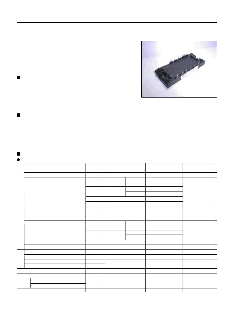
7MBR35UA120
IGBT Modules
IGBT MODULE (U series)
1200V / 35A / PIM
Features
· Low V
CE
(sat)
· Compact Package
· P.C. Board Mount Module
· Converter Diode Bridge Dynamic Brake Circuit
Applications
· Inverter for Motoe Drive
· AC and DC Servo Drive Amplifier
· Uninterruptible Power Supply
Maximum ratings and characteristics
Absolute maximum ratings (Tc=25°C unless otherwise specified)
Item Symbol Condition Rating Unit
Collector-Emitter voltage
Gate-Emitter voltage
Collector current
Collector power disspation
Collector-Emitter voltage
Gate-Emitter voltage
Collector current
Collector power disspation
Repetitive peak reverse voltage
Repetitive peak reverse voltage
Average output current
Surge current (Non-Repetitive)
I
2
t (Non-Repetitive)
C
Continuous
1ms
1ms
1 device
Continuous
1ms
1 device
50Hz/60Hz sine wave
Tj=150°C, 10ms
half sine wave
AC : 1 minute
1200
±20
35
25
70
50
35
70
160
1200
±20
25
15
50
30
115
1200
1600
35
260
338
+150
-40 to +125
AC 2500
AC 2500
3.5 *
1
V
V
A
W
V
V
A
W
V
V
A
A
A
2
s
°C
°C
V
N·m
*1
Recommendable value : 2.5 to 3.5 N·m (M5)
*2 All terminals should be connected together when isolation test will be done.
*3 Two thermistor terminals should be connected together, each other terminals should be
connected together and shorted to base plate when isolation test will be done.
Tc=25°C
Tc=80°C
Tc=25°C
Tc=80°C
Tc=25°C
Tc=80°C
Tc=25°C
Tc=80°C
相關(guān)PDF資料 |
PDF描述 |
|---|---|
| 7MBR50SA-060 | Power Integrated Module (PIM) |
| 7MBR50NF060 | 600V/50A/PIM |
| 7MBR50SA060 | IGBT(600V/50A/PIM) |
| 7MBR50SB060 | IGBT(600V/50A/PIM) |
| 7MBR50SB120 | IGBT(1200V/50A/PIM) |
相關(guān)代理商/技術(shù)參數(shù) |
參數(shù)描述 |
|---|---|
| 7MBR35UA-120 | 制造商:未知廠家 制造商全稱:未知廠家 功能描述:IGBTs |
| 7MBR35UA-120-50 | 制造商:Fuji Electric 功能描述:IGBT 7 PACK MOD 1200V 35A M711 |
| 7MBR35UB120 | 制造商:FUJI 制造商全稱:Fuji Electric 功能描述:IGBT MODULE (U series) 1200V / 35A / PIM |
| 7MBR35VM120-50 | 制造商:FUJI 制造商全稱:Fuji Electric 功能描述:IGBT MODULE |
| 7MBR35VP120-50 | 制造商:FUJI 制造商全稱:Fuji Electric 功能描述:IGBT MODULE |
發(fā)布緊急采購,3分鐘左右您將得到回復(fù)。