- 您現(xiàn)在的位置:買賣IC網(wǎng) > PDF目錄357314 > 48S15.3XT-HS 1-OUTPUT 45 W DC-DC REG PWR SUPPLY MODULE PDF資料下載
參數(shù)資料
| 型號: | 48S15.3XT-HS |
| 元件分類: | 電源模塊 |
| 英文描述: | 1-OUTPUT 45 W DC-DC REG PWR SUPPLY MODULE |
| 文件頁數(shù): | 5/8頁 |
| 文件大小: | 161K |
| 代理商: | 48S15.3XT-HS |

45 Watt XT Single Series DC/DC Converters
2401 Stanwell Drive Concord, California 94520 Ph: 925/687-4411 or 800/542-3355 Fax: 925/687-3333 www.calex.com Email: sales@calex.com
5
3/2001
Remote Sense
The XT single features provisions for remote sense
connections. These allow the power supply to correct for line
drops of up to 0.6 volts per side. The remote sense connections
should be made with twisted pair wire or closely coupled PCB
traces. If the remote sense is not to be used these pins must
be connected to their respective output pins for proper output
voltage accuracy and regulation. There is approximately 2 mA
of current flowing in the remote sense lines.
Care should be taken to not disconnect the output pins
before the remote sense pins while the converter is in operation.
If this happens the output load current will run down the sense
leads possibly causing an output overvoltage condition. If the
unit must be
“
Hot Plugged
”
in the intended application, provision
should be made to disconnect the sense leads before the
power leads, disconnect the input power first or use the
remote ON/OFF to stop the converters operation.
Another option is to attach two 1N4001 diodes from pins 6
to 3 and pins 7 to 5 as shown in figure 3. These diodes will
shunt any current through the 10 ohm internal resistors
connected between the outputs and their respective outputs
when the voltage drop across the resistors exceeds
approximately 0.6 volts. This will limit momentary overvoltages
to about 1.2 volts during a hot plug-in.
Output Trimming
The trim pin may be used to adjust the outputs by up to ±10
% from the nominal factory setting. The trim may be used to
adjust for system wiring voltage drops or to adjust the +5
output up to 5.2 volts for ECL applications. Figure 4 shows the
proper connections to use the trim pin. If output trimming is not
desired the trim pin may be safely left floating.
Trimming the output up reduces the output current
proportionally to keep the maximum power constant. Output
current is not increased over the listed maximum when
trimming the output voltage down.
Figure 4.
The output can be trimmed by either a trimpot or fixed resistors. If
fixed resistors are used their values may range from 0 to infinite
ohms. The trimpot should be 10k ohms for 3.3 and 5 volt outputs or
20k ohms for 12 and 15 volt outputs.
Non Standard Output Voltages
The 12 and 15 volt XT
’
s will typically trim much lower than the
-10% specified. This allows the 12 and 15 volt XT
’
s to be
trimmed lower than specified for RF or other special
applications.
The 12 volt XT
’
s can be typically trimmed over a range of
8.6 to 13.3 volts. The 15 volt XT
’
s can be typically trimmed
over a range of 9.8 to 16.8 volts.
Down trim actually can reduce the minimum input voltage
in some circuits. Full up trim may not be achievable at
minimum input voltage and full rated load.
The maximum current available does not increase from the
listed maximum under low trim conditions.
Ultra Low Noise Output Circuit
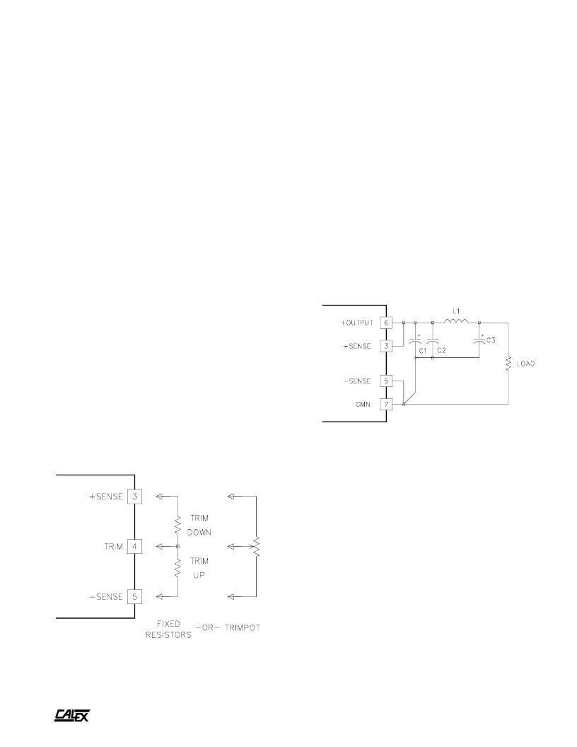
The circuit shown in figure 5 can be used to reduce the output
noise to below 10 mV P-P over a 20 MHz bandwidth. Size
inductor L1 appropriately for the maximum expected load
current. The remote sense lines should be looped back
directly to the output pins to prevent feedback loop oscillation
due to the filters extra phase shift.
Figure 5.
For very low noise applications this circuit will reduce the output
noise to less than 10 mV P-P over a 0-20 MHz bandwidth. Be sure
to size the inductor appropriately for the maximum expected load
current.
Operation With Light Loads
At output loads less than specified minimum, the XT single will
operate in a
“
Burst Mode
”
. That is the XT will cease PWM
operation and instead operate in more of a burst mode. This
mode significantly reduces the light load input current to the
XT single. Under these conditions the output of the XT will
contain a larger than normal (compared to full load) output
noise, but at a lower frequency.
If this is a problem in your application the XT single may be
used with a dummy load resistor to keep the static output
current above the specified mimimum load.
相關(guān)PDF資料 |
PDF描述 |
|---|---|
| 48S5.8XT-HS-1 | 1-OUTPUT 45 W DC-DC REG PWR SUPPLY MODULE |
| 49-59-313R | PUSHBUTTON SWITCH, SPST, MOMENTARY, 0.1A, 50VDC, PANEL MOUNT-THREADED |
| 4903-S | SHIELDED, 0.086 uH - 0.107 uH, VARIABLE INDUCTOR |
| 4904 | UNSHIELDED, 0.148 uH - 0.252 uH, VARIABLE INDUCTOR |
| 4907-RC | UNSHIELDED, 0.286 uH - 0.508 uH, VARIABLE INDUCTOR |
相關(guān)代理商/技術(shù)參數(shù) |
參數(shù)描述 |
|---|---|
| 48S5.3000BR | 制造商:CALEX 功能描述: |
| 48SC-003A-M2 | 制造商:JVC Worldwide 功能描述:SCREEN ASSY |
| 48SC004 | 功能描述:塑料硬件 SPEAKER CLIP RoHS:否 制造商:3M Electronic Specialty 類型:Cylindrical Bumpers |
| 48SD1616 | 制造商:MAXWELL 制造商全稱:Maxwell Technologies 功能描述:256 Mb SDRAM 4-Meg X 16-Bit X 4-Banks |
| 48SD1616RPFE | 制造商:MAXWELL 制造商全稱:Maxwell Technologies 功能描述:256 Mb SDRAM 4-Meg X 16-Bit X 4-Banks |
發(fā)布緊急采購,3分鐘左右您將得到回復(fù)。