- 您現(xiàn)在的位置:買賣IC網(wǎng) > PDF目錄357314 > 48S15.3XT-HS 1-OUTPUT 45 W DC-DC REG PWR SUPPLY MODULE PDF資料下載
參數(shù)資料
| 型號(hào): | 48S15.3XT-HS |
| 元件分類: | 電源模塊 |
| 英文描述: | 1-OUTPUT 45 W DC-DC REG PWR SUPPLY MODULE |
| 文件頁數(shù): | 4/8頁 |
| 文件大?。?/td> | 161K |
| 代理商: | 48S15.3XT-HS |

A
45 Watt XT Single Series DC/DC Converters
2401 Stanwell Drive Concord, California 94520 Ph: 925/687-4411 or 800/542-3355 Fax: 925/687-3333 www.calex.com Email: sales@calex.com
4
3/2001
Applying the Input
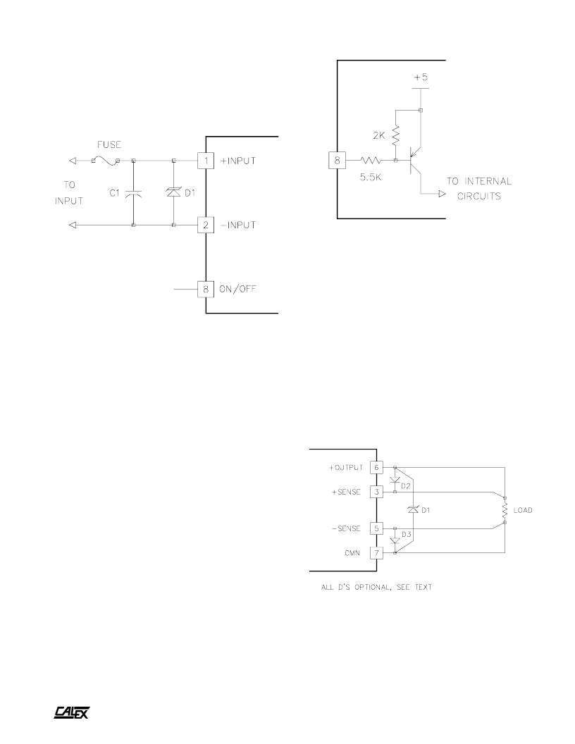
Figure 1 shows the recommended input connections for the
XT Single DC/DC converter. A fuse is recommended to
protect the input circuit and should not be omitted. The fuse
serves to prevent unlimited current from flowing in the case of
a catastrophic system failure.
Figure 1.
Standard connections for the XT single input. The ON/OFF pin may
be left floating if it is not used. The input protection fuse should not
be omitted. If desired, an external transient protection diode (D1)
can be used at the input. See
“
Applying the input
”
for suggestions
regarding C1.
No external capacitance on the input is required for normal
operation, in fact it can degrade the converters performance.
Extremely low ESR capacitors (< 0.5 ohms) should not be
used at the input as this will cause peaking of the input filters
transfer function and actually degrade the filters performance.
Normal RF bypass capacitors in the 1000 pF to 0.01 μF range
may be used without harm.
Remote ON/OFF Pin Operation
The remote ON/OFF pin may be left floating if this function is
not used. The equivalent input circuit for the ON/OFF pin is
shown in figure 2. The best way to drive this pin is with an open
collector/drain or relay contact. See our application note titled
“
Understanding the remote ON/OFF function
”
for more
information about using the remote ON/OFF pin.
When the ON/OFF pin is pulled low with respect to the -
Input, the converter is placed in a low power drain state. The
ON/OFF pin turns the converter off while keeping the input
bulk capacitor fully charged, this prevents the large inrush
current spike that occurs when the +input pin is opened and
closed.
Figure 2.
The simplified schematic of the XT Single series ON/OFF pin. The
input impedance is approximately 6k ohms. By leaving this pin
floating the converter will be in the ON state. When the pin is pulled
below 1.4 volts (with respect to the -Input pin) the converter is placed
in the power down or OFF state. See our application note on the
remote ON/OFF function for more information.
Applying The Output
Figure 3 shows typical output connections for the XT single.
In most applications no external output capacitance will be
necessarily. Only your normal 1 to 10 μF and 0.001 to 0.1 μF
bypass capacitors sprinkled around your circuit as needed
locally are required. Do not add extra output capacitance and
cost to your circuit
“
Just Because
”
.
If you feel you must add external output capacitance, do
not use the lowest ESR, biggest value capacitor that you can
find! This can only lead to reduced system performance or
oscillation. See our application note
“
Understanding Output
Impedance For Optimum Decoupling
”
for more information.
Figure 3.
The remote sense lines should be connected to their respective
output pins even if they are not used in your application. If desired,
an external transient protection diode can be used. D2 and D3 are
optional, for more information see the
“
Remote sense
”
section.
相關(guān)PDF資料 |
PDF描述 |
|---|---|
| 48S5.8XT-HS-1 | 1-OUTPUT 45 W DC-DC REG PWR SUPPLY MODULE |
| 49-59-313R | PUSHBUTTON SWITCH, SPST, MOMENTARY, 0.1A, 50VDC, PANEL MOUNT-THREADED |
| 4903-S | SHIELDED, 0.086 uH - 0.107 uH, VARIABLE INDUCTOR |
| 4904 | UNSHIELDED, 0.148 uH - 0.252 uH, VARIABLE INDUCTOR |
| 4907-RC | UNSHIELDED, 0.286 uH - 0.508 uH, VARIABLE INDUCTOR |
相關(guān)代理商/技術(shù)參數(shù) |
參數(shù)描述 |
|---|---|
| 48S5.3000BR | 制造商:CALEX 功能描述: |
| 48SC-003A-M2 | 制造商:JVC Worldwide 功能描述:SCREEN ASSY |
| 48SC004 | 功能描述:塑料硬件 SPEAKER CLIP RoHS:否 制造商:3M Electronic Specialty 類型:Cylindrical Bumpers |
| 48SD1616 | 制造商:MAXWELL 制造商全稱:Maxwell Technologies 功能描述:256 Mb SDRAM 4-Meg X 16-Bit X 4-Banks |
| 48SD1616RPFE | 制造商:MAXWELL 制造商全稱:Maxwell Technologies 功能描述:256 Mb SDRAM 4-Meg X 16-Bit X 4-Banks |
發(fā)布緊急采購,3分鐘左右您將得到回復(fù)。