- 您現(xiàn)在的位置:買賣IC網(wǎng) > PDF目錄357314 > 48IML10-12-12-0C (POWER-ONE INC) 2-OUTPUT 10.8 W DC-DC REG PWR SUPPLY MODULE PDF資料下載
參數(shù)資料
| 型號: | 48IML10-12-12-0C |
| 廠商: | POWER-ONE INC |
| 元件分類: | 電源模塊 |
| 英文描述: | 2-OUTPUT 10.8 W DC-DC REG PWR SUPPLY MODULE |
| 封裝: | 2 X 1 INCH, 10.50 MM HEIGHT, MODULE-5 |
| 文件頁數(shù): | 5/5頁 |
| 文件大小: | 66K |
| 代理商: | 48IML10-12-12-0C |

Board Mountable
DC-DC Converters
IML 10 Series
Edition 6/10.2001 R1
5/5
AC-DC
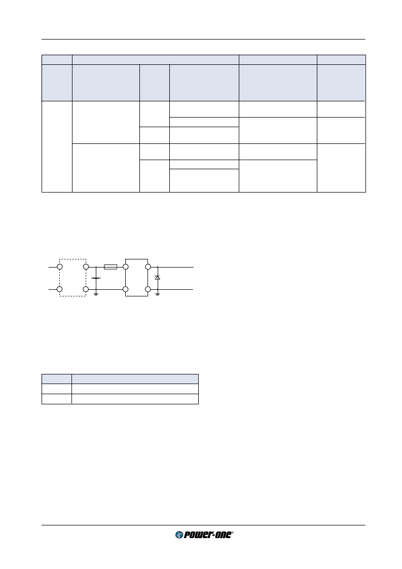
front
end
DC-DC
con-
verter
Mains
~
Fuse
Battery
Earth
connection
Suppressor
diode
SELV
Earth
connection
+
–
~
10004
Fig. 4
Schematic safety concept. Use fuse, suppressor diode
and earth connection as per table: Safety concept leading
to an SELV output circuit.
Table 5: Insulation concept leading to an SELV output circuit
Conditions Front end
DC-DC converter
Result
Supply
voltage
Minimum required grade
of isolation, to be provided DC output
by the AC-DC front end,
including mains supplied
battery charger
Maximum
Minimum required safety
status of the front end
output circuit
Measures to achieve the
specified safety status of the
output circuit
Safety status of
the DC-DC
converter output
circuit
voltage
from the
front end
1
Mains
≤
250 V AC
Basic
≤
60 V
Earthed SELV circuit
2
Operational insulation, pro-
vided by the DC-DC converter
SELV circuit
ELV circuit
Input fuse
3
output suppressor
diode(s)
4
, and earthed
output circuit(s)
2
Earthed SELV
circuit
>60 V
Hazardous voltage
secondary circuit
Double or reinforced
≤
60 V
SELV circuit
Operational insulation, pro-
vided by the DC-DC converter
SELV circuit
>60 V
TNV-2 circuit
Supplementary insulation,
based on the maximum input
voltage, provided by the
DC-DC converter
Double or reinforced insu-
lated unearthed hazardous
voltage secondary circuit
5
1
The front end output voltage should match the specified input voltage range of the DC-DC converter.
2
The earth connection has to be provided by the installer according to the relevant safety standard, e.g. IEC/EN 60950.
3
The installer shall provide an approved fuse (type with the lowest rating suitable for the application) in the non-earthed input line di-
rectly at the input of the DC-DC converter (see fig.: Schematic safety concept). For UL
’
s purpose, the fuse needs to be UL-listed. See
also: Input Fuse
4
Each suppressor diode should be dimensioned in such a way, that in the case of an insulation fault the diode is able to limit the output
voltage to SELV (<60 V) until the input fuse blows (see fig.: Schematic safety concept).
5
Has to be insulated from earth by basic insulation according to the relevant safety standard, based on the maximum output voltage
from the front end.
Accessories
Mounting supports for chassis and DIN-rail mounting.
Option C
The C-pinout configures the electrically isolated double out-
puts to the "industrial pinout" Vo1+, Vo2
–
with common
ground Go. With the C-pinout the converter height is in-
creased by the adapter PCB (see also: Mechanical Data).
Description of Options
Table 6: Survey of options
Option
Function of option
C
C-pinout
Z
Open frame
相關(guān)PDF資料 |
PDF描述 |
|---|---|
| 48IMP3-1212-7S | 2-OUTPUT 3 W DC-DC REG PWR SUPPLY MODULE |
| 48S12.850TC | 1-OUTPUT 10 W DC-DC REG PWR SUPPLY MODULE |
| 48S15.3XT-HS | 1-OUTPUT 45 W DC-DC REG PWR SUPPLY MODULE |
| 48S5.8XT-HS-1 | 1-OUTPUT 45 W DC-DC REG PWR SUPPLY MODULE |
| 49-59-313R | PUSHBUTTON SWITCH, SPST, MOMENTARY, 0.1A, 50VDC, PANEL MOUNT-THREADED |
相關(guān)代理商/技術(shù)參數(shù) |
參數(shù)描述 |
|---|---|
| 48IML10-12-12-3 | 制造商:POWER-ONE 制造商全稱:Power-One 功能描述:10 Watt DC-DC Converters |
| 48IML10-12-3C | 制造商:POWER-ONE 制造商全稱:Power-One 功能描述:10 Watt DC-DC Converters |
| 48IML10-15-15-3 | 功能描述:CONVERT DC/DC 2X 15V 10W RoHS:否 類別:電源 - 板載 >> DC DC Converters 系列:* 標(biāo)準(zhǔn)包裝:5 系列:* |
| 48IML10-15-3C | 制造商:POWER-ONE 制造商全稱:Power-One 功能描述:10 Watt DC-DC Converters |
| 48IMO6-03-2 | 制造商:POWER-ONE 制造商全稱:Power-One 功能描述:6 Watt DC-DC Converters |
發(fā)布緊急采購,3分鐘左右您將得到回復(fù)。