- 您現(xiàn)在的位置:買賣IC網(wǎng) > PDF目錄357314 > 48IML10-12-12-0C (POWER-ONE INC) 2-OUTPUT 10.8 W DC-DC REG PWR SUPPLY MODULE PDF資料下載
參數(shù)資料
| 型號: | 48IML10-12-12-0C |
| 廠商: | POWER-ONE INC |
| 元件分類: | 電源模塊 |
| 英文描述: | 2-OUTPUT 10.8 W DC-DC REG PWR SUPPLY MODULE |
| 封裝: | 2 X 1 INCH, 10.50 MM HEIGHT, MODULE-5 |
| 文件頁數(shù): | 4/5頁 |
| 文件大小: | 66K |
| 代理商: | 48IML10-12-12-0C |

Board Mountable
DC-DC Converters
IML 10 Series
Edition 6/10.2001 R1
4/5
Safety and Installation Instructions
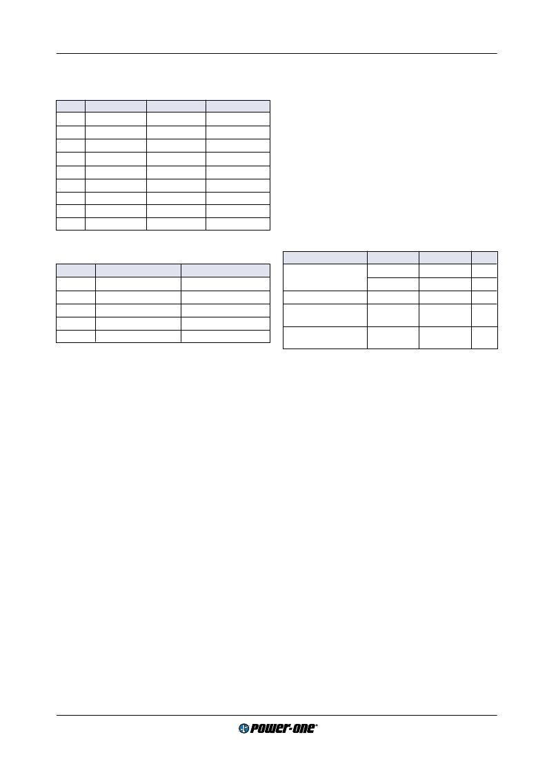
Table 2: Pin allocation IML
Pin
Single output
0503 types
Double outputs
1
Vi+
Vi+
Vi+
2
Vi
–
Vi
–
Vi
–
3
n.c.
n.c.
n.c.
4
n.c.
n.c.
n.c.
10
Vo
–
Go
Vo1
–
11
Vo+
Vo1+
Vo1+
12
Vo
–
Go
Vo2
–
13
n.c.
Vo2+
Vo2+
14
n.c.
n.c.
n.c.
Table 3: C pinout (option C)
Pin
Single output
Dual output
1
Vi+
Vi+
2
Vi
–
Vi
–
3
Vo+
Vo+
4
no pin
Go
5
Vo
–
Vo
–
Installation Instruction
Installation of the DC-DC converters must strictly follow the
national safety regulations in compliance with the enclo-
sure, mounting, creepage, clearance, casualty, markings
and segregation requirements of the end-use application.
Connection to the system shall be made via a printed circuit
board according to: Mechanical Data
The units should be connected to a secondary circuit.
Check for hazardous voltages before altering any connec-
tions.
Do not open the module.
Ensure that a unit failure (e.g. by an internal short-circuit)
does not result in a hazardous condition. See also: Safety
of operator accessible output circuit.
Input Fuse
To prevent excessive current flowing through the input sup-
ply line in case of a short-circuit across the converter input
an external fuse should be installed in a non earthed input
supply line. We recommend a fast acting fuse F2A for
24 IML 10 types and F1A for 48 IML 10 types.
Cleaning Agents
In order to avoid possible damage, any penetration of
cleaning fluids has to be prevented, since the power sup-
plies are not hermetically sealed.
Standards and approvals
All DC-DC converters are pending to be UL recognized ac-
cording to UL 1950, UL recognized for Canada to CAN/
CSA C22.2 No. 950-95 and LGA approved to IEC/EN
60950 standards.
The units have been evaluated for:
Building in
Supplementary insulation input to output, based on their
maximum input voltage
The use in a pollution degree 2 environment
Connecting the input to a secondary circuit which is sub-
ject to a maximum transient rating of 1500 V
The DC-DC converters are subject to manufacturing sur-
veillance in accordance with the above mentioned UL,
CSA, EN and ISO 9001 standards.
Isolation
The electric strength test is performed as factory test in ac-
cordance with IEC/EN 60950 and UL 1950 and should not
be repeated in the field. Power-One will not honour any
guarantee claims resulting from electric strength field tests.
Table 4: Electric strength test voltages, clearance and
creepage distances
Characteristic
I/O
O/O
Unit
Electric strength
test voltage 1 s
1.2
0.1
kV
rms
1.5
0.15
kV DC
Coupling capacitance
≈
1.2
-
nF
Isulation resistance
at 500 V DC
>100
-
M
Partial discharge
extinction voltage
Consult
factory
-
kV
Protection Degree
The protection degree of the DC-DC converters is IP 30.
Safety of operator accessible output circuit
If the output circuit of a DC-DC converter is operator acces-
sible, it shall be an SELV circuit according to IEC/EN 60950
related safety standards
The insulation concept table below shows some possible
installation configurations, compliance with which causes
the output circuit of the DC-DC converter to be an SELV cir-
cuit according to IEC/EN 60950 up to a configured output
voltage (sum of nominal voltages if in series or +/
–
configu-
ration) of 30 V.
However, it is the sole responsibility of the installer to en-
sure the compliance with the relevant and applicable safety
regulations. More information is given in: Technical Infor-
mation:Safety
相關(guān)PDF資料 |
PDF描述 |
|---|---|
| 48IMP3-1212-7S | 2-OUTPUT 3 W DC-DC REG PWR SUPPLY MODULE |
| 48S12.850TC | 1-OUTPUT 10 W DC-DC REG PWR SUPPLY MODULE |
| 48S15.3XT-HS | 1-OUTPUT 45 W DC-DC REG PWR SUPPLY MODULE |
| 48S5.8XT-HS-1 | 1-OUTPUT 45 W DC-DC REG PWR SUPPLY MODULE |
| 49-59-313R | PUSHBUTTON SWITCH, SPST, MOMENTARY, 0.1A, 50VDC, PANEL MOUNT-THREADED |
相關(guān)代理商/技術(shù)參數(shù) |
參數(shù)描述 |
|---|---|
| 48IML10-12-12-3 | 制造商:POWER-ONE 制造商全稱:Power-One 功能描述:10 Watt DC-DC Converters |
| 48IML10-12-3C | 制造商:POWER-ONE 制造商全稱:Power-One 功能描述:10 Watt DC-DC Converters |
| 48IML10-15-15-3 | 功能描述:CONVERT DC/DC 2X 15V 10W RoHS:否 類別:電源 - 板載 >> DC DC Converters 系列:* 標(biāo)準(zhǔn)包裝:5 系列:* |
| 48IML10-15-3C | 制造商:POWER-ONE 制造商全稱:Power-One 功能描述:10 Watt DC-DC Converters |
| 48IMO6-03-2 | 制造商:POWER-ONE 制造商全稱:Power-One 功能描述:6 Watt DC-DC Converters |
發(fā)布緊急采購,3分鐘左右您將得到回復(fù)。