- 您現(xiàn)在的位置:買賣IC網(wǎng) > PDF目錄371435 > 28F160C3 (INTEL CORP) 3 Volt Advanced Boot Block Flash Memory(3 V 高級(jí)快速引導(dǎo)塊閃速存儲(chǔ)器) PDF資料下載
參數(shù)資料
| 型號(hào): | 28F160C3 |
| 廠商: | INTEL CORP |
| 元件分類: | DRAM |
| 英文描述: | 3 Volt Advanced Boot Block Flash Memory(3 V 高級(jí)快速引導(dǎo)塊閃速存儲(chǔ)器) |
| 中文描述: | 8M X 8 FLASH 3V PROM |
| 文件頁數(shù): | 50/59頁 |
| 文件大小: | 321K |
| 代理商: | 28F160C3 |
第1頁第2頁第3頁第4頁第5頁第6頁第7頁第8頁第9頁第10頁第11頁第12頁第13頁第14頁第15頁第16頁第17頁第18頁第19頁第20頁第21頁第22頁第23頁第24頁第25頁第26頁第27頁第28頁第29頁第30頁第31頁第32頁第33頁第34頁第35頁第36頁第37頁第38頁第39頁第40頁第41頁第42頁第43頁第44頁第45頁第46頁第47頁第48頁第49頁當(dāng)前第50頁第51頁第52頁第53頁第54頁第55頁第56頁第57頁第58頁第59頁
28F800C3, 28F160C3, 28F320C3
E
50
PRELIMINARY
C.3
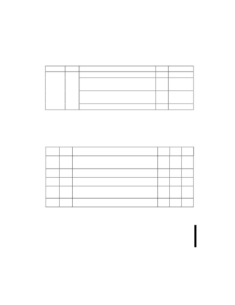
BLOCK LOCK STATUS REGISTER
The Block Status Register indicates whether an erase operation completed successfully or whether a given
block is locked or can be accessed for flash program/erase operations.
Block Erase Status (BSR.1) allows system software to determine the success of the last block erase
operation. BSR.1 can be used just after power-up to verify that the V
CC
supply was not accidentally removed
during an erase operation. This bit is only reset by issuing another erase operation to the block. The Block
Status Register is accessed from word address 02h within each block.
Table C4. Block Status Register
Offset
Length
Description
Add.
Value
(BA+2)h
(1)
1
Block Lock Status Register
BA+2:
--00 or --01
BSR.0 Block Lock Status
0 = Unlocked
1 = Locked
BA+2:
(bit 0): 0 or 1
BSR.1 Block Lock-Down Status
0 = Not locked down
1 = Locked down
BA+2:
(bit 1): 0 or 1
BSR 2
–7:
Reserved for future use
BA+2:
(bit 2–7): 0
NOTE:
1.
BA = The beginning location of a Block Address (i.e., 008000h is the beginning location of block 1 in word mode.)
C.4
CFI QUERY IDENTIFICATION STRING
The Identification String provides verification that the component supports the Common Flash Interface
specification. It also indicates the specification version and supported vendor-specified command set(s).
Table 5. CFI Identification
Offset
Length
Description
Add.
Hex
Code
--51
--52
--59
--03
--00
--35
--00
--00
Value
10h
3
Query-unique ASCII string “QRY“
10
11:
12:
13:
14:
15:
16:
17:
“Q”
“R”
“Y”
13h
2
Primary vendor command set and control interface ID code.
16-bit ID code for vendor-specified algorithms
Extended Query Table primary algorithm address
15h
2
17h
2
Alternate vendor command set and control interface ID
code.
0000h means no second vendor-specified algorithm exists
Secondary algorithm Extended Query Table address.
0000h means none exists
18:
19:
1A:
--00
--00
--00
19h
2
相關(guān)PDF資料 |
PDF描述 |
|---|---|
| 28F320D18 | 1.8 Volt Intel Dual-Plane Flash Memory(1.8 V Intel 雙平面閃速存儲(chǔ)器) |
| 28F320J5 | 5 Volt Intel StrataFlash Memory(5 V 32M位英特爾StrataFlash存儲(chǔ)器) |
| 28F640J5 | 5 V Intel StrataFlash Memory(5V 64M位英特爾StrataFlash閃速存儲(chǔ)器) |
| 28F400B3 | SMART 3 ADVANCED BOOT BLOCK WORD-WIDE |
| 28F400BL-TB | 4-MBlT (256K x 16, 512K x 8) LOW-POWER BOOT BLOCK FLASH MEMORY FAMILY |
相關(guān)代理商/技術(shù)參數(shù) |
參數(shù)描述 |
|---|---|
| 28F160C3BA90 | 制造商: 功能描述: 制造商:Intel 功能描述: 制造商:undefined 功能描述: |
| 28F160C3TD70 | 制造商: 功能描述: 制造商:undefined 功能描述: |
| 28F160F3 | 制造商:未知廠家 制造商全稱:未知廠家 功能描述:FAST BOOT BLOCK FLASH MEMORY FAMILY 8 AND 16 MBIT |
| 28F160F3B95 | 制造商:Intel 功能描述: |
| 28F160S3 | 制造商:INTEL 制造商全稱:Intel Corporation 功能描述:WORD-WIDE FlashFile MEMORY FAMILY |
發(fā)布緊急采購,3分鐘左右您將得到回復(fù)。