- 您現(xiàn)在的位置:買賣IC網(wǎng) > PDF目錄372952 > XTR501 XTR501 - HIGH CURRENT BRIDGE DRIVER and 4-20mA Transmitter PDF資料下載
參數(shù)資料
| 型號(hào): | XTR501 |
| 英文描述: | XTR501 - HIGH CURRENT BRIDGE DRIVER and 4-20mA Transmitter |
| 中文描述: | XTR501 -大電流橋式驅(qū)動(dòng)器和4 - 20mA變送器 |
| 文件頁數(shù): | 6/7頁 |
| 文件大?。?/td> | 68K |
| 代理商: | XTR501 |
XTR501
6
FIGURE 1. Basic Connection
TYPICAL PERFORMANCE CURVES
(CONT)
T
A
= +25
°
C, V
S
= 24V, V
BRIDGE
= 2V, I
LOAD
= 300mA unless otherwise specified.
METHOD OF OPERATION
The XTR501 consists of a high efficiency DC/DC converter
with current and voltage mode control and a current loop
transmitter.
The pulse-width modulation controller monitors the current
and voltage control signals and varies the conduction period
to regulate the bridge excitation voltage, V
B
.
A soft-start feature is provided to negate problems caused by
high in-rush currents and lead resistances, thus allowing the
XTR501 to be driven through cables of up to 100
of supply
line resistance with no reduction in performance.
A single resistor, R
SET
, determines the regulated bridge
excitation voltage which may be in the range 1.5V to 5.0V.
The gain of the transconductance amplifier, which forms the
current loop transmitter, is again determined by a single
resistor R
and allows input voltages from 25mV to drive
the 4-20mA current loop.
APPLICATIONS
The XTR501 is designed to be used with a wide range of
pellistor catalytic gas detectors. The pellistor gas detector
consists of a matched pair of elements; an active bead which
is the sensing element, and an inactive bead which is the
compensating element. These elements form one side of a
Wheatstone bridge arrangement. The bridge serves a dual
purpose: to raise the temperature of the elements to about
500
°
C, which is their working temperature, and to allow
detection of the presence of combustible gases through imbal-
ance of the bridge. This happens as the pellistor increases
temperature due to oxidation of the flammable gas and thus
increases its resistance.
In general, pellistor catalytic gas detectors are limited in use
to monitoring up to 100% of the LEL (lower explosive
limit). Beyond this point ambiguous results can occur due to
the inability of the pellistor to oxidize the gas as the avail-
able oxygen decreases (see Figure 3).
LEL Methane
Bridge Voltage V
EX
=
=
=
=
=
5% = V
IN
= 50mV
2.0V
21.858k
4-20mA
510
R
SET
I
O
R
SPAN
XTR501
+V
B
+V
BSENSE
– V
B
COM
–V
IN
3
+V
IN
22
10k
100
V
BB
R
T
R
SPAN
G
ASET
G
ASENSE
G
BSENSE
G
BSET
R
SET
100
470μH
I
O
= 4 to 20mA
(1)
NOTE: (1) VQ 21 Gas Sensor - EEV Gas Sensors.
V
BSET
I
O
10μF
Tantalum
+24V
R
250
15
18
17
11
16
24
23
1
2
10
14
12
V
S
5μF
Tantalum
V
OUT
1V to 5V
V
OUT
= I
O
R
LOAD
+
+
Compensator
Detector
0
30
60
90
120
150
16
14
12
10
8
6
4
2
0
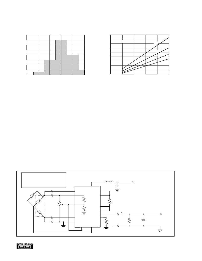
BRIDGE EXCITATION VOLTAGE TC (ppm/°C)
Bridge Excitation Voltage Temperature Drift (ppm/°C)
Average =
3
σ
= 70ppm/°C
N
SUPPLY CURRENT vs EXCITATION LOAD CURRENT
I
LOAD
(
mA)
S
110
100
90
80
70
60
50
40
30
20
100
200
300
400
500
0
Bridge Voltage (V
EX
) = 2.0V
V
S
= 24V
V
S
= 18V
V
S
= 13.5V
V
S
=30V
相關(guān)PDF資料 |
PDF描述 |
|---|---|
| XTTEK100Q56 | PSU 100W 4 O/P U FRAME |
| XTTEK100Q86 | PSU 100W 4 O/P U FRAME |
| XTTEK100S01 | PSU 5V 20A L FRAME |
| XTTEK100S02 | PSU 12V 8.5A L FRAME |
| XTTEK100S04 | PSU 24V 4.5A L FRAME |
相關(guān)代理商/技術(shù)參數(shù) |
參數(shù)描述 |
|---|---|
| XTR560 | 制造商: 功能描述: 制造商:undefined 功能描述: |
| XTR7020A4 | 制造商:AUREL 功能描述:RF MOD TXRX FSK 434MHZ 115.2KBPS 制造商:AUREL 功能描述:RF MOD, TXRX, FSK, 434MHZ, 115.2KBPS 制造商:AUREL 功能描述:RF MOD, TXRX, FSK, 434MHZ, 115.2KBPS, Frequency Min:433.19MHz, Frequency Max:434 |
| XTR7020A8 | 制造商:AUREL 功能描述:RF MOD TXRX FSK 868MHZ 115.2KBPS 制造商:AUREL 功能描述:RF MOD, TXRX, FSK, 868MHZ, 115.2KBPS 制造商:AUREL 功能描述:RF MOD, TXRX, FSK, 868MHZ, 115.2KBPS, Frequency Min:869.19MHz, Frequency Max:869 |
| XTRE10B22A | 制造商:Eaton Corporation 功能描述:CONTROL RELAY; 4 POLE (2NO-2NC); 16 AMP; FRAME B; 120VAC |
| XTRE10B22AD | 制造商:Moeller Electric Corporation 功能描述:Control Relay 10A Frame B 2NO2NC 120VDC Coil |
發(fā)布緊急采購,3分鐘左右您將得到回復(fù)。