- 您現(xiàn)在的位置:買賣IC網(wǎng) > PDF目錄10012 > XRT6164CP-F (Exar Corporation)IC TXRX DGTL INTERFACE 16PDIP PDF資料下載
參數(shù)資料
| 型號: | XRT6164CP-F |
| 廠商: | Exar Corporation |
| 文件頁數(shù): | 5/10頁 |
| 文件大?。?/td> | 0K |
| 描述: | IC TXRX DGTL INTERFACE 16PDIP |
| 標(biāo)準(zhǔn)包裝: | 25 |
| 類型: | 收發(fā)器 |
| 驅(qū)動器/接收器數(shù): | 1/1 |
| 電源電壓: | 4.75 V ~ 5.25 V |
| 安裝類型: | 通孔 |
| 封裝/外殼: | 16-DIP(0.300",7.62mm) |
| 供應(yīng)商設(shè)備封裝: | 16-PDIP |
| 包裝: | 管件 |
XRT6164
4
Rev. 4.0.0
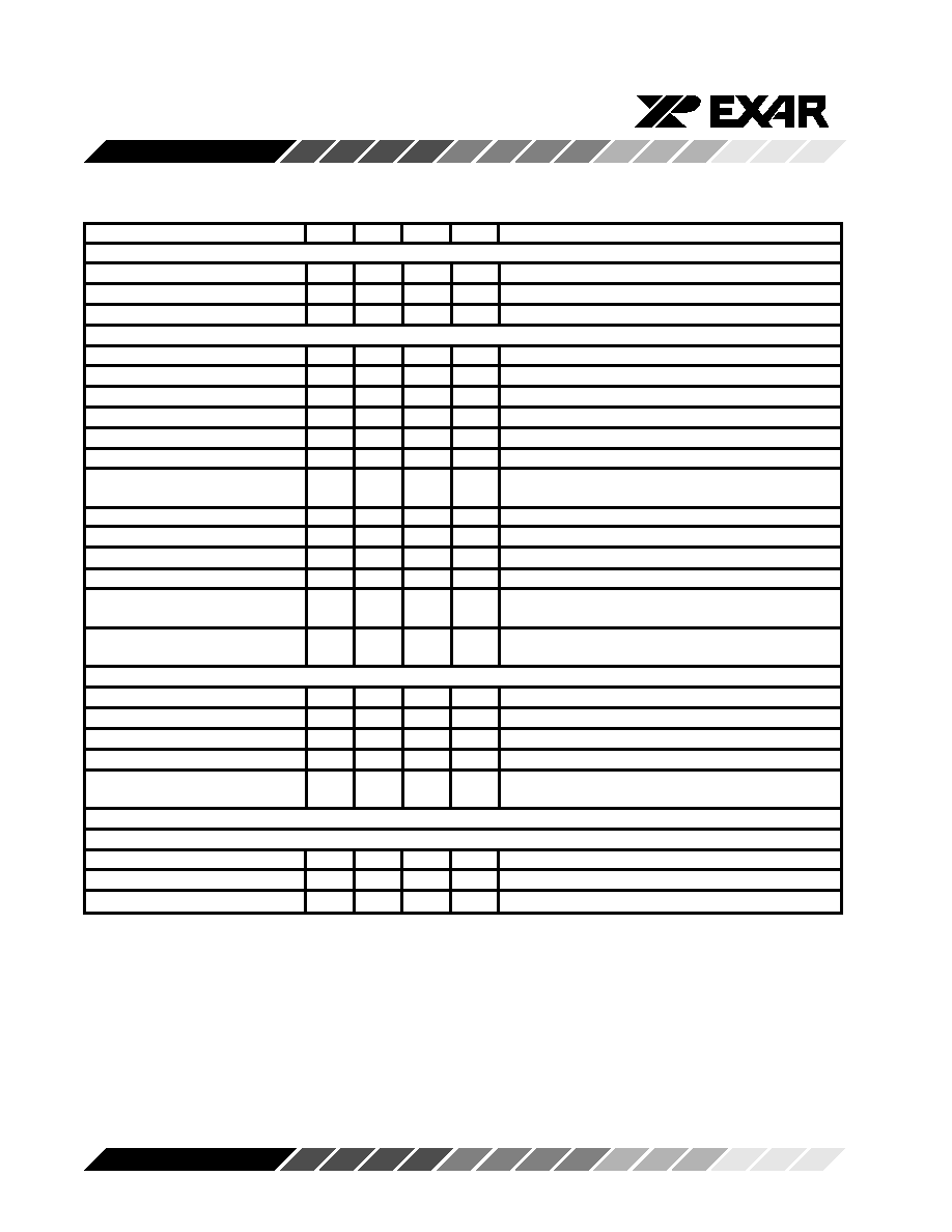
ELECTRICAL CHARACTERISTICS
Test Conditions: V
CC = 5V +/- 5%, T A = 25°C, Unless Otherwise Specified
Parameters
Min.
Typ.
Max. Units
Conditions
DC Electrical Characteristics
Supply Voltage
4.75
5
5.25
V
Analog Supply Current
48
mA
Digital Supply Current
13
20
mA
Receiver
Input Signal
1
2.2
Vp
Measured from Pins 1 or 16 with Respect to Pin 2
Dynamic Range
10
d B
Maximum Cable Loss Range
Input Impedance
20
k
Ω
Measured Between Pins 1 and 16
Input Slicing Threshold
50
%
Percent of Peak Input Signal Amplitude
Input Bias Voltage
1.45
V
Measured at Pin 2
Loss of Signal Alarm Threshold
150
mVp
Measured from Pins 1 or 16 with Respect to Pin 2
Loss of Signal Alarm Level
+/-1.5
d B
Difference Between Alarm-on and Alarm-off
Hysteresis
Levels
Peak Detector Leakage
-80
μA
Data Output Low
0.4
V
Measured at Pins 5 or 12, I OUT = +1.6mA
Data Output High
3.6
V
Measured at Pins 5 or 12, I OUT = -40
μA
Alarm Output Low
0.4
V
Measured at Pin 3; I OUT = +1.6mA
Alarm Output High
V
CC -
V
Measured at Pin 3; I OUT = -40
μA
0.5
TCM Input Low Voltage
0.8
V
Measured at Pin 15; I IN Min = -500
μA, I IN Max =
+5
μA
Transmitter
Input Low Voltage
0.8
V
Measured at Pins 6, 11; I IN = -700
μA
Input High Voltage
2.2
V
Measured at Pins 6, 11; I IN = +5
μA
Output Low Voltage
1
V
Measured at Pins 8, 10; I OUT = -40mA
Output Low Current
40
mA
Measured at Pins 8, 10; V OUT = 1V
Output Leakage Current
-100
μA
Measured at Pins 8, 10; V OUT = 10V Outputs in
off state
AC Electrical Characteristics
Receiver
Input Level
1
2.2
Vp
Pin 1, 16 with Respect to Pin 2 1
Output Rise Time
50
n s
Pins 5, 12; C L = 15pF, 10% to 90%
Output Fall Time
50
n s
Pins 5, 12; C L =15pF, 90% to 10%
Notes:
1. Higher input voltages are possible if a resistive input attenuator is used.
Bold face parameters are covered by production test and guaranteed over operating temperature range.
相關(guān)PDF資料 |
PDF描述 |
|---|---|
| IDT72V3632L10PF8 | IC BIFIFO 512X36X2 10NS 120-TQFP |
| VI-2WV-MY | CONVERTER MOD DC/DC 5.8V 50W |
| LTC1345ISW#PBF | IC TXRX V.35 SINGL SUPPLY 28SOIC |
| VI-B3L-MX-B1 | CONVERTER MOD DC/DC 28V 75W |
| LTC1345ISW | IC TXRX V.35 SINGL SUPPLY 28SOIC |
相關(guān)代理商/技術(shù)參數(shù) |
參數(shù)描述 |
|---|---|
| XRT6164CP-F | 制造商:Exar Corporation 功能描述:IC LINE INTERFACE TXRX DIP-16 |
| XR-T6165 | 制造商:EXAR 制造商全稱:EXAR 功能描述:Codirectional Digital Data Processor |
| XR-T6165CD | 制造商:EXAR 制造商全稱:EXAR 功能描述:Codirectional Digital Data Processor |
| XR-T6165CD-F | 制造商:Exar Corporation 功能描述:Digital Data Processor 1TX 1RX 2.048Mbps 24-Pin SOIC W 制造商:EXAR 功能描述:Digital Data Processor 1TX 1RX 2.048Mbps 24-Pin SOIC W |
| XRT6165CD-F | 功能描述:外圍驅(qū)動器與原件 - PCI 5V 8.192MHz RoHS:否 制造商:PLX Technology 工作電源電壓: 最大工作溫度: 安裝風(fēng)格:SMD/SMT 封裝 / 箱體:FCBGA-1156 封裝:Tray |
發(fā)布緊急采購,3分鐘左右您將得到回復(fù)。