- 您現(xiàn)在的位置:買賣IC網(wǎng) > PDF目錄16555 > XR16M681IL32-0C-EB (Exar Corporation)EVAL BOARD FOR XR16M681-C 32QFN PDF資料下載
參數(shù)資料
| 型號: | XR16M681IL32-0C-EB |
| 廠商: | Exar Corporation |
| 文件頁數(shù): | 23/51頁 |
| 文件大小: | 0K |
| 描述: | EVAL BOARD FOR XR16M681-C 32QFN |
| 標準包裝: | 1 |
| 系列: | * |
第1頁第2頁第3頁第4頁第5頁第6頁第7頁第8頁第9頁第10頁第11頁第12頁第13頁第14頁第15頁第16頁第17頁第18頁第19頁第20頁第21頁第22頁當前第23頁第24頁第25頁第26頁第27頁第28頁第29頁第30頁第31頁第32頁第33頁第34頁第35頁第36頁第37頁第38頁第39頁第40頁第41頁第42頁第43頁第44頁第45頁第46頁第47頁第48頁第49頁第50頁第51頁
XR16M681
3
REV. 1.0.1
1.62V TO 3.63V UART WITH 32-BYTE FIFO AND VLIO INTERFACE
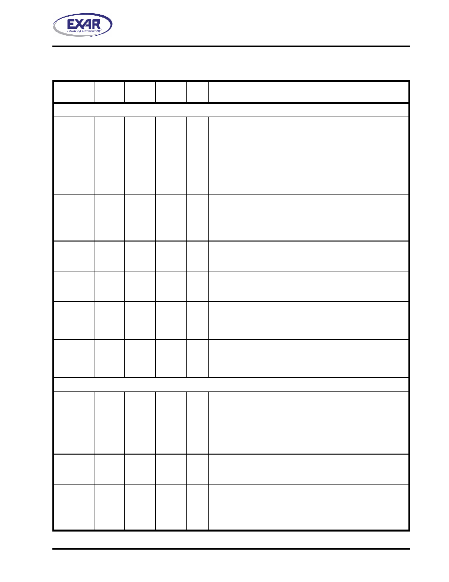
PIN DESCRIPTIONS
Pin Description
NAME
24-QFN
PIN#
32-QFN
PIN#
25-BGA
PIN#
TYPE
DESCRIPTION
DATA BUS INTERFACE
AD0
AD1
AD2
AD3
AD4
AD5
AD6
AD7
20
21
22
23
24
1
2
3
29
30
31
32
1
3
4
5
C1
D2
E2
D1
E1
B2
E3
C2
I/O
Multiplexed Address/Data lines [7:0]. The register address is
latched on the rising edge of the LLA#. After the LLA# signal goes
high, the UART enters the data phase where the data is placed on
these lines.
IOR#
12
14
A5
I
Read strobe (active low). The falling edge instigates an internal
read cycle and retrieves the data byte from an internal register
pointed by the latched address. The UART places the data byte on
the data bus to allow the host processor to read it on the rising
edge.
IOW#
10
12
E5
I
Write strobe (active low). The falling edge instigates the internal
write cycle and the rising edge transfers the data byte on the data
bus to an internal register pointed by the latched address.
CS#
6
8
D3
I
Chip select (active low). The falling edge starts the access to the
UART. A read or write is determined by the IOR# and IOW# sig-
nals.
LLA#
14
19
A4
I
Latch Lower Address (active low). The register address is latched
on the rising edge of the LLA# signal. After the LLA# goes high, the
device enters the data phase where the data is placed on the
AD[7:0] lines.
INT
15
20
B4
O
Interrupt output (active high). The output state is defined by the
user through the software setting of MCR[3]. INT is set to the active
mode when MCR[3] is set to a logic 1. INT is set to the three state
mode when MCR[3] is set to a logic 0. See MCR[3].
MODEM OR SERIAL I/O INTERFACE
TX
5
7
E4
O
UART Transmit Data or infrared encoder data. Standard transmit
and receive interface is enabled when MCR[6] = 0. In this mode,
the TX signal will be a logic 1 during reset or idle (no data). Infrared
IrDA transmit and receive interface is enabled when MCR[6] = 1. In
the Infrared mode, the inactive state (no data) for the Infrared
encoder/decoder interface is a logic 0. If it is not used, leave it
unconnected.
RX
4
6
C3
I
UART Receive Data or infrared receive data. Normal receive data
input must idle at logic 1 condition. The infrared receiver idles at
logic 0. This input should be connected to VCC when not used.
RTS#
16
21
A3
O
UART Request-to-Send (active low) or general purpose output.
This output must be asserted prior to using auto RTS flow control,
see EFR[6], MCR[1] and IER[6]. This pin can also be used as the
Auto RS-485 Half-duplex Direction control output, see FCTR[3] and
EMSR[3].
相關PDF資料 |
PDF描述 |
|---|---|
| H3CWH-2618G | IDC CABLE - HKC26H/AE26G/HPL26H |
| EMM12DRSS | CONN EDGECARD 24POS DIP .156 SLD |
| MAX8662ETM+T | IC PMIC LI+ SNGL CELL 48TQFN |
| H3AWH-3406M | IDC CABLE - HSC34H/AE34M/HPL34H |
| H3CKH-3406M | IDC CABLE - HKC34H/AE34M/HPK34H |
相關代理商/技術參數(shù) |
參數(shù)描述 |
|---|---|
| XR16M681IL32-F | 功能描述:UART 接口集成電路 1.62-3.63V; 32-Byte FIFO & VLIO; UART RoHS:否 制造商:Texas Instruments 通道數(shù)量:2 數(shù)據(jù)速率:3 Mbps 電源電壓-最大:3.6 V 電源電壓-最小:2.7 V 電源電流:20 mA 最大工作溫度:+ 85 C 最小工作溫度:- 40 C 封裝 / 箱體:LQFP-48 封裝:Reel |
| XR16M698 | 制造商:EXAR 制造商全稱:EXAR 功能描述:1.62V TO 3.63V HIGH PERFORMANCE OCTAL UART WITH 32-BYTE FIFO |
| XR16M698IQ-0A-EVB | 功能描述:界面開發(fā)工具 Eval Board for XR16M698IQ-0A RoHS:否 制造商:Bourns 產(chǎn)品:Evaluation Boards 類型:RS-485 工具用于評估:ADM3485E 接口類型:RS-485 工作電源電壓:3.3 V |
| XR16M698IQ-0B-EVB | 功能描述:界面開發(fā)工具 Eval Board for XR16M698IQ-0B RoHS:否 制造商:Bourns 產(chǎn)品:Evaluation Boards 類型:RS-485 工具用于評估:ADM3485E 接口類型:RS-485 工作電源電壓:3.3 V |
| XR16M698IQ100 | 制造商:EXAR 制造商全稱:EXAR 功能描述:1.62V TO 3.63V HIGH PERFORMANCE OCTAL UART WITH 32-BYTE FIFO |
發(fā)布緊急采購,3分鐘左右您將得到回復。