- 您現(xiàn)在的位置:買賣IC網(wǎng) > PDF目錄4057 > XCS10XL-5VQ100C (Xilinx Inc)IC FPGA 3.3V C-TEMP 100-VQFP PDF資料下載
參數(shù)資料
| 型號: | XCS10XL-5VQ100C |
| 廠商: | Xilinx Inc |
| 文件頁數(shù): | 18/83頁 |
| 文件大小: | 0K |
| 描述: | IC FPGA 3.3V C-TEMP 100-VQFP |
| 產(chǎn)品變化通告: | Product Discontinuation 26/Oct/2011 |
| 標(biāo)準(zhǔn)包裝: | 90 |
| 系列: | Spartan®-XL |
| LAB/CLB數(shù): | 196 |
| 邏輯元件/單元數(shù): | 466 |
| RAM 位總計: | 6272 |
| 輸入/輸出數(shù): | 77 |
| 門數(shù): | 10000 |
| 電源電壓: | 3 V ~ 3.6 V |
| 安裝類型: | 表面貼裝 |
| 工作溫度: | 0°C ~ 85°C |
| 封裝/外殼: | 100-TQFP |
| 供應(yīng)商設(shè)備封裝: | 100-VQFP(14x14) |
第1頁第2頁第3頁第4頁第5頁第6頁第7頁第8頁第9頁第10頁第11頁第12頁第13頁第14頁第15頁第16頁第17頁當(dāng)前第18頁第19頁第20頁第21頁第22頁第23頁第24頁第25頁第26頁第27頁第28頁第29頁第30頁第31頁第32頁第33頁第34頁第35頁第36頁第37頁第38頁第39頁第40頁第41頁第42頁第43頁第44頁第45頁第46頁第47頁第48頁第49頁第50頁第51頁第52頁第53頁第54頁第55頁第56頁第57頁第58頁第59頁第60頁第61頁第62頁第63頁第64頁第65頁第66頁第67頁第68頁第69頁第70頁第71頁第72頁第73頁第74頁第75頁第76頁第77頁第78頁第79頁第80頁第81頁第82頁第83頁
Spartan and Spartan-XL FPGA Families Data Sheet
DS060 (v2.0) March 1, 2013
25
Product Specification
R
Product Obsolete/Under Obsolescence
Power-down retains the configuration, but loses all data
stored in the device flip-flops. All inputs are interpreted as
Low, but the internal combinatorial logic is fully functional.
Make sure that the combination of all inputs Low and all
flip-flops set or reset in your design will not generate internal
oscillations, or create permanent bus contention by activat-
ing internal bus drivers with conflicting data onto the same
long line.
During configuration, the PWRDWN pin must be High. If the
Power Down state is entered before or during configuration,
the device will restart configuration once the PWRDWN sig-
nal is removed. Note that the configuration pins are affected
by Power Down and may not reflect their normal function. If
there is an external pull-up resistor on the DONE pin, it will
be High during Power Down even if the device is not yet
configured. Similarly, if PWRDWN is asserted before config-
uration is completed, the INIT pin will not indicate status
information.
Note that the PWRDWN pin is not part of the Boundary
Scan chain. Therefore, the Spartan-XL family has a sepa-
rate set of BSDL files than the 5V Spartan family. Boundary
scan logic is not usable during Power Down.
Configuration and Test
Configuration is the process of loading design-specific pro-
gramming data into one or more FPGAs to define the func-
tional
operation
of
the
internal
blocks
and
their
interconnections. This is somewhat like loading the com-
mand registers of a programmable peripheral chip.
Spartan/XL devices use several hundred bits of configura-
tion data per CLB and its associated interconnects. Each
configuration bit defines the state of a static memory cell
that controls either a function look-up table bit, a multiplexer
input, or an interconnect pass transistor. The Xilinx develop-
ment system translates the design into a netlist file. It auto-
matically partitions, places and routes the logic and
generates the configuration data in PROM format.
Configuration Mode Control
5V Spartan devices have two configuration modes.
MODE = 1 sets Slave Serial mode
MODE = 0 sets Master Serial mode
3V Spartan-XL devices have three configuration modes.
M1/M0 = 11 sets Slave Serial mode
M1/M0 = 10 sets Master Serial mode
M1/M0 = 0X sets Express mode
In addition to these modes, the device can be configured
through the Boundary Scan logic (See "Configuration
The Mode pins are sampled prior to starting configuration to
determine the configuration mode. After configuration,
these pin are unused. The Mode pins have a weak pull-up
resistor turned on during configuration. With the Mode pins
High, Slave Serial mode is selected, which is the most pop-
ular configuration mode. Therefore, for the most common
configuration mode, the Mode pins can be left unconnected.
If the Master Serial mode is desired, the MODE/M0 pin
should be connected directly to GND, or through a
pull-down resistor of 1 K
Ω or less.
During configuration, some of the I/O pins are used tempo-
rarily for the configuration process. All pins used during con-
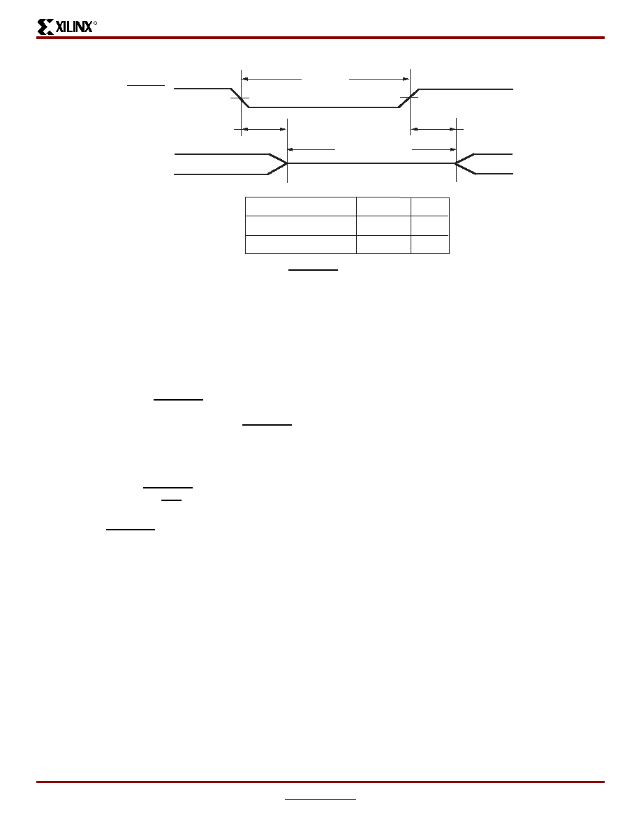
Figure 23: PWRDWN Pulse Timing
Power Down Mode
50 ns
TPWDW
TPWD
TPWDW
Outputs
PWRDWN
Description
Power Down Time
Power Down Pulse Width
Symbol
Min
50 ns
DS060_23_041901
相關(guān)PDF資料 |
PDF描述 |
|---|---|
| XCS10XL-5TQ144C | IC FPGA 3.3V C-TEMP 144-TQFP |
| IDT7015S15J | IC SRAM 72KBIT 15NS 68PLCC |
| FMM43DSEH-S243 | CONN EDGECARD 86POS .156 EYELET |
| IDT71V67803S166BG | IC SRAM 9MBIT 166MHZ 119BGA |
| AMM43DTMS-S189 | CONN EDGECARD 86POS R/A .156 SLD |
相關(guān)代理商/技術(shù)參數(shù) |
參數(shù)描述 |
|---|---|
| XCS10XL-5VQ100I | 制造商:XILINX 制造商全稱:XILINX 功能描述:Spartan and Spartan-XL Families Field Programmable Gate Arrays |
| XCS10XL-5VQ144C | 制造商:XILINX 制造商全稱:XILINX 功能描述:Spartan and Spartan-XL Families Field Programmable Gate Arrays |
| XCS10XL-5VQ144I | 制造商:XILINX 制造商全稱:XILINX 功能描述:Spartan and Spartan-XL Families Field Programmable Gate Arrays |
| XCS10XL-5VQ208C | 制造商:XILINX 制造商全稱:XILINX 功能描述:Spartan and Spartan-XL Families Field Programmable Gate Arrays |
| XCS10XL-5VQ208I | 制造商:XILINX 制造商全稱:XILINX 功能描述:Spartan and Spartan-XL Families Field Programmable Gate Arrays |
發(fā)布緊急采購,3分鐘左右您將得到回復(fù)。