- 您現(xiàn)在的位置:買(mǎi)賣(mài)IC網(wǎng) > PDF目錄371300 > X9421YVI-2.7 Single Digitally Controlled (XDCP) Potentiometer PDF資料下載
參數(shù)資料
| 型號(hào): | X9421YVI-2.7 |
| 元件分類(lèi): | 數(shù)字電位計(jì) |
| 英文描述: | Single Digitally Controlled (XDCP) Potentiometer |
| 中文描述: | 單數(shù)控(數(shù)字電位器)電位 |
| 文件頁(yè)數(shù): | 1/21頁(yè) |
| 文件大小: | 117K |
| 代理商: | X9421YVI-2.7 |
當(dāng)前第1頁(yè)第2頁(yè)第3頁(yè)第4頁(yè)第5頁(yè)第6頁(yè)第7頁(yè)第8頁(yè)第9頁(yè)第10頁(yè)第11頁(yè)第12頁(yè)第13頁(yè)第14頁(yè)第15頁(yè)第16頁(yè)第17頁(yè)第18頁(yè)第19頁(yè)第20頁(yè)第21頁(yè)
REV 1.1.6 8/1/02
Characteristics subject to change without notice.
1 of 21
www.xicor.com
X9421
Single Digitally Controlled (XDCP) Potentiometer
FEATURES
Single Voltage Potentiometer
64 Resistor Taps
SPI Serial Interface for write, read, and transfer
operations of the potentiometer
Wiper Resistance, 150
4 Non-Volatile Data Registers
Non-Volatile Storage of Multiple Wiper Positions
Power On Recall. Loads Saved Wiper Position on
Power Up.
Standby Current < 5μA Max
V
CC
: 2.7V to 5.5V Operation
2.5K
, 10K
End to End Resistance
100 yr. Data Retention
Endurance: 100, 000 Data Changes per Bit per
Register
14-Lead TSSOP, 16-Lead SOIC
Low Power CMOS
Typical at 5V
DESCRIPTION
The X9421 integrates a single digitally controlled
potentiometer (XDCP) on a monolithic CMOS
integrated circuit.
The digital controlled potentiometer is implemented
using 63 resistive elements in a series array. Between
each element are tap points connected to the wiper
terminal through switches. The position of the wiper on
the array is controlled by the user through the SPI bus
interface. The potentiometer has associated with it a
volatile Wiper Counter Register (WCR) and a four non-
volatile Data Registers that can be directly written to
and read by the user. The contents of the WCR
controls the position of the wiper on the resistor array
though the switches. Powerup recalls the contents of
the default data register (DR0) to the WCR.
The XDCP can be used as a three-terminal
potentiometer or as a two terminal variable resistor in
a wide variety of applications including control,
parameter adjustments, and signal processing.
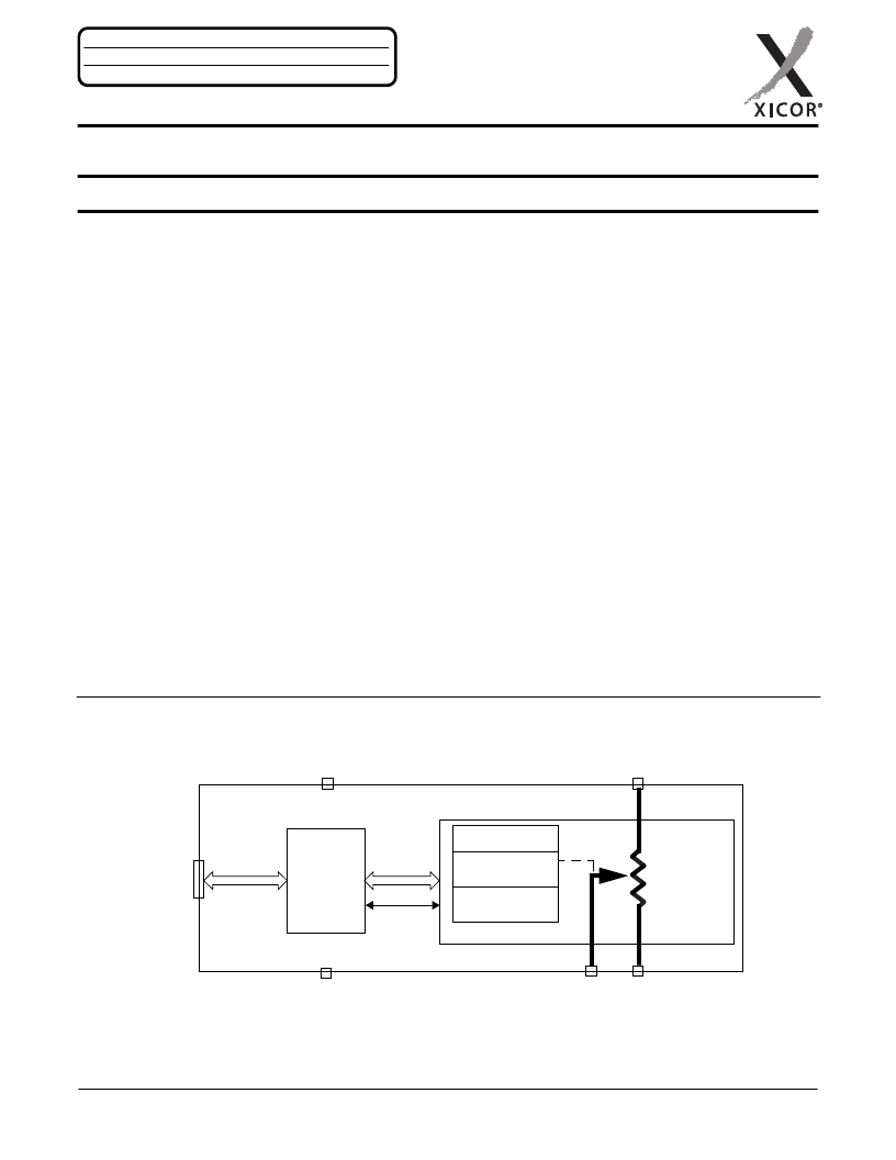
BLOCK DIAGRAM
64-taps
10K
inc / dec
R
H
/V
H
R
L
/V
L
R
W
/V
W
POT
V
CC
V
SS
SPI
bus
interface
address
data
status
write
trread
wiper
Power On Recall
Wiper Counter
Register (WCR)
Data Registers
4 Bytes
control
Bus
Interface &
Control
Low Noise/Low Power/SPI Bus
A
PPLICATION
N
OTES
A V A I L A B L E
AN99 AN115 AN120 AN124 AN133 AN134 AN135
相關(guān)PDF資料 |
PDF描述 |
|---|---|
| X9421WS16 | Single Digitally Controlled (XDCP) Potentiometer |
| X9421WS16-2.7 | Single Digitally Controlled (XDCP) Potentiometer |
| X9421WS16I | Single Digitally Controlled (XDCP) Potentiometer |
| X9421WS16IZ | Single Digitally Controlled (XDCP) Potentiometer |
| X9421WS16IZ-2.7 | Single Digitally Controlled (XDCP) Potentiometer |
相關(guān)代理商/技術(shù)參數(shù) |
參數(shù)描述 |
|---|---|
| X9428 | 制造商:INTERSIL 制造商全稱(chēng):Intersil Corporation 功能描述:Single Digitally Controlled Potentiometer |
| X9428_06 | 制造商:INTERSIL 制造商全稱(chēng):Intersil Corporation 功能描述:Single Digitally Controlled Potentiometer |
| X9428MP | 制造商:未知廠家 制造商全稱(chēng):未知廠家 功能描述:Industrial Control IC |
| X9428MP2.7 | 制造商:未知廠家 制造商全稱(chēng):未知廠家 功能描述:Industrial Control IC |
| X9428MPI | 制造商:未知廠家 制造商全稱(chēng):未知廠家 功能描述:Industrial Control IC |
發(fā)布緊急采購(gòu),3分鐘左右您將得到回復(fù)。