- 您現在的位置:買賣IC網 > PDF目錄245692 > W3H64M72E-533ESM (WHITE ELECTRONIC DESIGNS CORP) 64M X 72 DDR DRAM, 0.5 ns, PBGA208 PDF資料下載
參數資料
| 型號: | W3H64M72E-533ESM |
| 廠商: | WHITE ELECTRONIC DESIGNS CORP |
| 元件分類: | DRAM |
| 英文描述: | 64M X 72 DDR DRAM, 0.5 ns, PBGA208 |
| 封裝: | 17 X 23 MM, 1 MM PITCH, PLASTIC, BGA-208 |
| 文件頁數: | 7/30頁 |
| 文件大?。?/td> | 999K |
| 代理商: | W3H64M72E-533ESM |
第1頁第2頁第3頁第4頁第5頁第6頁當前第7頁第8頁第9頁第10頁第11頁第12頁第13頁第14頁第15頁第16頁第17頁第18頁第19頁第20頁第21頁第22頁第23頁第24頁第25頁第26頁第27頁第28頁第29頁第30頁
W3H64M72E-XSBX
15
White Electronic Designs Corporation (602) 437-1520 www.wedc.com
White Electronic Designs
December 2006
Rev. 2
ADVANCED*
White Electronic Designs Corp. reserves the right to change products or specications without notice.
EXTENDED MODE REGISTER 2
The extended mode register 2 (EMR2) controls functions
beyond those controlled by the mode register. Currently
all bits in EMR2 are reserved, as shown in Figure 8. The
EMR2 is programmed via the LM command and will
retain the stored information until it is programmed again
or the device loses power. Reprogramming the EMR will
not alter the contents of the memory array, provided it is
performed correctly.
Bit E7 (A7) must be programmed as"1" to provide a faster
refresh rate on devices if the TCASE exceeds 85°C
EMR2 must be loaded when all banks are idle and no
bursts are in progress, and the controller must wait the
specied time tMRD before initiating any subsequent
operation. Violating either of these requirements could
result in unspecied operation.
EXTENDED MODE REGISTER 3
The extended mode register 3 (EMR3) controls functions
beyond those controlled by the mode register. Currently,
all bits in EMR3 are reserved, as shown in Figure 9.
The EMR3 is programmed via the LM command and will
retain the stored information until it is programmed again
or the device loses power. Reprogramming the EMR will
not alter the contents of the memory array, provided it is
performed correctly.
EMR3 must be loaded when all banks are idle and no
bursts are in progress, and the controller must wait the
specied time tMRD before initiating any subsequent
operation. Violating either of these requirements could
result in unspecied operation.
COMMAND TRUTH TABLES
The following tables provide a quick reference of DDR2
SDRAM available commands, including CKE power-down
modes, and bank-to-bank commands.
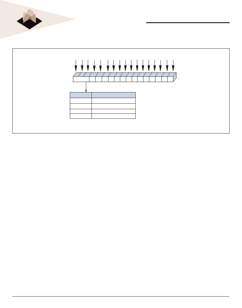
FIGURE 9 – EXTENDED MODE REGISTER 3 (EMR3) DEFINITION
A9
A7 A 6 A5 A4 A3
A8
A2
A1 A0
Exten ded Mo de
Re gister (Ex)
Address Bus
97
6
5
4
3
82
1
0
A10
A12 A11
BA0
BA1
10
11
12
13
14
15
A13
0
1
0
1
Mode Register Definition
M15
0
0
1
M14
EMR3
01
BA2
16
M1 6
0
0
Mode register (MR)
Extended mode register (EMR)
Extended mode register (EMR2)
Extended mode register (EMR3)
Note: 1. E13 (A13)-E0 (A0) are reserved for future use and must be programmed to
"0." A13 is not used in this device.
相關PDF資料 |
PDF描述 |
|---|---|
| WPS256K16T-20LJI | 256K X 16 STANDARD SRAM, 20 ns, PDSO44 |
| WMF256K8-70FEI5 | 256K X 8 FLASH 5V PROM, 70 ns, CDFP32 |
| WMF256K8-70DEC5A | 256K X 8 FLASH 5V PROM, 70 ns, CDSO32 |
| WMF256K8-90DEM5 | 256K X 8 FLASH 5V PROM, 90 ns, CDSO32 |
| WMS512K8BV-17CME | 512K X 8 STANDARD SRAM, 17 ns, CDIP32 |
相關代理商/技術參數 |
參數描述 |
|---|---|
| W3H64M72E-533SB | 制造商:WEDC 制造商全稱:White Electronic Designs Corporation 功能描述:64M x 72 DDR2 SDRAM 208 PBGA Multi-Chip Package |
| W3H64M72E-533SBC | 制造商:Microsemi Corporation 功能描述:64M X 72 DDR2, 1.8V, 533MHZ, 208PBGA COMMERICAL TEMP. - Bulk |
| W3H64M72E-533SBI | 制造商:Microsemi Corporation 功能描述:64M X 72 DDR2, 1.8V, 533MHZ, 208PBGA INDUSTRIAL TEMP. - Bulk 制造商:Microsemi Corporation 功能描述:SDRAM MEMORY |
| W3H64M72E-533SBM | 制造商:Microsemi Corporation 功能描述:64M X 72 DDR2, 1.8V, 533MHZ, 208PBGA MIL-TEMP. - Bulk |
| W3H64M72E-667ES | 制造商:WEDC 制造商全稱:White Electronic Designs Corporation 功能描述:64M x 72 DDR2 SDRAM 208 PBGA Multi-Chip Package |
發(fā)布緊急采購,3分鐘左右您將得到回復。