- 您現(xiàn)在的位置:買賣IC網(wǎng) > PDF目錄202808 > VT-800-DFJ-406A-16M0000000 (VECTRON INTERNATIONAL) TCVCXO, CLIPPED SINE OUTPUT, 16 MHz PDF資料下載
參數(shù)資料
| 型號: | VT-800-DFJ-406A-16M0000000 |
| 廠商: | VECTRON INTERNATIONAL |
| 元件分類: | TCVCXO, sine |
| 英文描述: | TCVCXO, CLIPPED SINE OUTPUT, 16 MHz |
| 封裝: | ROHS COMPLIANT, HERMETIC SEALED, CERAMIC, SMD, 4 PIN |
| 文件頁數(shù): | 2/5頁 |
| 文件大?。?/td> | 0K |
| 代理商: | VT-800-DFJ-406A-16M0000000 |
Vectron International 267 Lowell Road, Hudson, NH 03051 Tel: 1-88-VECTRON-1 http://www.vectron.com
Description
Page2
Performance Specifications
Table 1. Electrical Performance
Parameter
Symbol
Min.
Typ
Max
Units
Output Frequency, +5V option
+2.8, +3.0, +3.3V options
f
O
10
27
40
MHz
Supply Voltage1
V
DD
+2.8, +3.0, +3.3 or +5.0
V
Supply Current, 8 to 14.999MHz
15.000 to 25.9999MHz
26.000 to 40.000MHz
I
DD
1.5
2.0
2.5
mA
Operating Temperature, ordering option
T
OP
0/55, -10/60, -20/70, -30/80, -40/85
°C
Stability Over TOP, ordering option
±0.5, ±1.0, ±.5, ±2.0, ±2.5, ±3.0, ±4.0, ±5.0
ppm
Initial Accuracy, “No Adjust” Option
±1.0
ppm
Power Supply Stability
±0.2
ppm
Load Stability
±0.2
ppm
Aging
±1.0
ppm/yr
Pull Range, ordering option
TPR
±5, ±8, ±10, ±12
ppm
Control Voltage to reach Pull Range
0.5
2.5
V
Control Voltage Impedance
1
Mohm
Output Level2
V
O
p/p
0.8
V
Output Load
10K II 10pF
Phase Noise, 10.000MHz
10Hz
100Hz
1kHz
10kHz
100kHz
-91
-116
-137
-149
-150
dBc/Hz
Start Up Time
10
ms
1. The VT-800 power supply pin should be filtered, eg, a 0.1 and 0.01uf capacitor
2. The Output is DC coupled
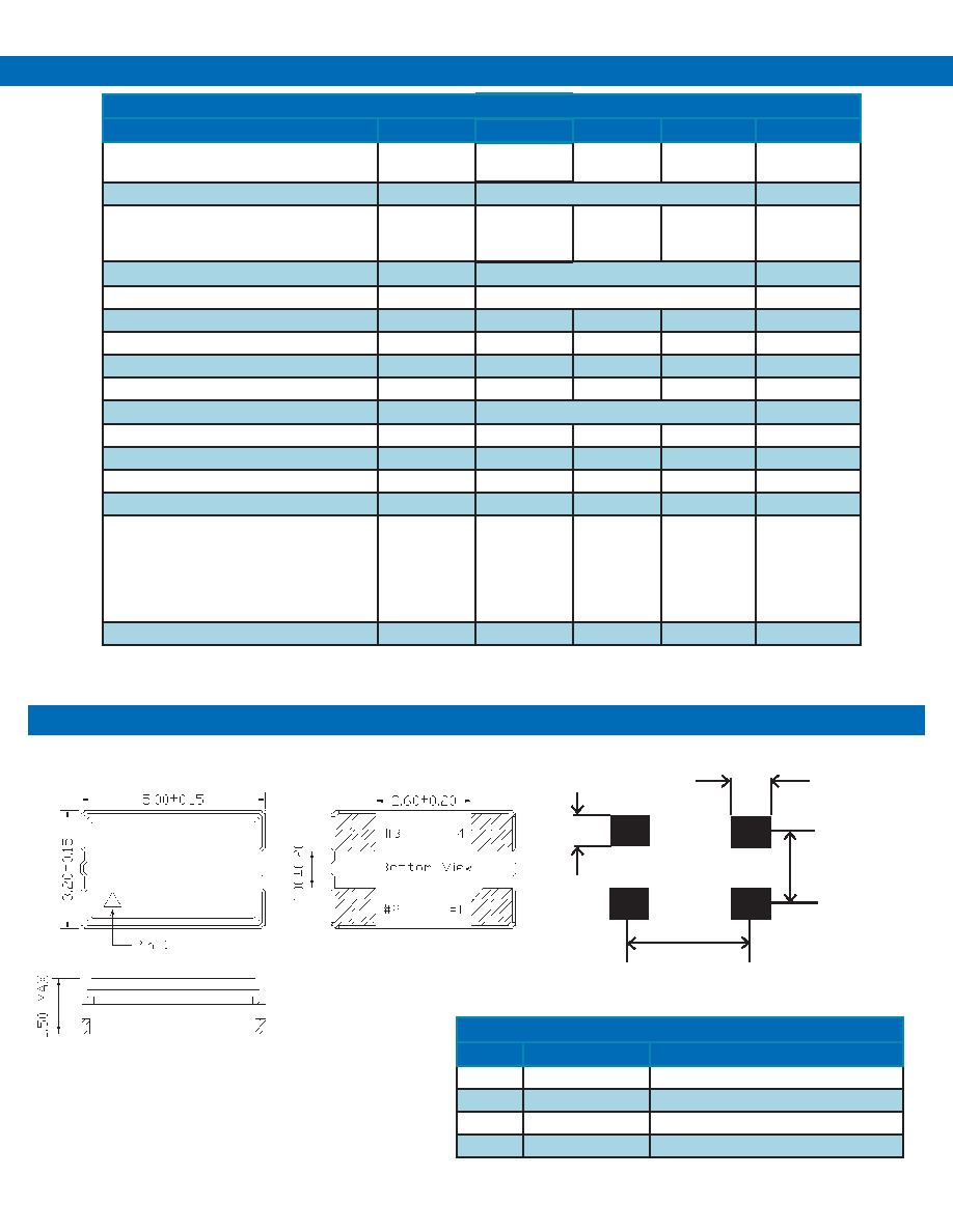
Table 2. Pinout
Pin #
Symbol
Function
1V
C
TCXO Control Voltage or Ground
2
GND
Electrical and Lid Ground
3f
o
Output Frequency
4V
DD
Supply Voltage
Dimensions in mm
Specifications
Outline Drawing
Recommended Pad Layout
1.4
2.3
3.8
1.1
Frequency
Date Code
相關(guān)PDF資料 |
PDF描述 |
|---|---|
| VT-800-FFG-356D-26M0000000 | TCVCXO, CLIPPED SINE OUTPUT, 26 MHz |
| VT-800-FFG-406A-25M0000000 | TCVCXO, CLIPPED SINE OUTPUT, 25 MHz |
| VT-800-DFK-356B-24M5535000 | TCVCXO, CLIPPED SINE OUTPUT, 24.5535 MHz |
| VT-800-DFK-356C-13M0000000 | TCVCXO, CLIPPED SINE OUTPUT, 13 MHz |
| VT-800-DFK-356C-24M5760000 | TCVCXO, CLIPPED SINE OUTPUT, 24.576 MHz |
相關(guān)代理商/技術(shù)參數(shù) |
參數(shù)描述 |
|---|---|
| VT-802 | 制造商:VECTRON 制造商全稱:Vectron International, Inc 功能描述:Temperature Compensated Crystal Oscillator |
| VT-802_12 | 制造商:VECTRON 制造商全稱:Vectron International, Inc 功能描述:Temperature Compensated Crystal Oscillator |
| VT-803 | 制造商:VECTRON 制造商全稱:Vectron International, Inc 功能描述:Temperature Compensated Crystal Oscillator |
| VT-803-EAE-287B-26M0000000 | 功能描述:TCXO振蕩器 26MHz 280ppb 3.3Volt -40 to 85C RoHS:否 制造商:AVX 封裝 / 箱體: 頻率:32.768 kHz 頻率穩(wěn)定性: 負(fù)載電容:15 pF 端接類型:SMD/SMT 電源電壓:3 V 尺寸:2.5 mm W x 3.2 mm L x 1 mm H 輸出格式:CMOS 最小工作溫度:- 40 C 最大工作溫度:+ 85 C 封裝:Reel |
| VT-803-EAH-507A | 制造商:VECTRON 制造商全稱:Vectron International, Inc 功能描述:Temperature Compensated Crystal Oscillator |
發(fā)布緊急采購,3分鐘左右您將得到回復(fù)。